Pioneer AVH-P2300DVD Owner's Manual - Page 68
Installation using the screw, holes on the side of the unit - install kit
 |
UPC - 884938124508
View all Pioneer AVH-P2300DVD manuals
Add to My Manuals
Save this manual to your list of manuals |
Page 68 highlights
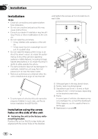
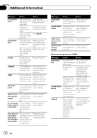
Section 15 Installation Installation Notes ! Check all connections and systems before final installation. ! Do not use unauthorized parts as this may cause malfunctions. ! Consult your dealer if installation requires dril- ling of holes or other modifications to the vehicle. ! Do not install this unit where: - it may interfere with operation of the vehi- cle. - it may cause injury to a passenger as a re- sult of a sudden stop. ! Do not install the display where it may (i) ob- struct the driver's vision, (ii) impair the performance of any of the vehicle's operating systems or safety features, including air bags, hazard lamp buttons or (iii) impair the driver's ability to safely operate the vehicle. ! The semiconductor laser will be damaged if it overheats. Install this unit away from hot places such as near the heater outlet. ! Optimum performance is obtained when the unit is installed at an angle of less than 30°. ! To some types of vehicles, this unit cannot be properly installed. In such case, use the optional installation kit (ADT-VA133). Installation using the screw holes on the side of the unit % Fastening the unit to the factory radiomounting bracket. Position the unit so that its screw holes are aligned with the screw holes of the bracket, and tighten the screws at 3 or 4 locations on each side. 1 2 3 4 5 1 If the pawl gets in the way, bend it down. 2 Factory radio mounting bracket 3 Use either truss (5 mm × 8 mm) or flush surface (5 mm × 9 mm) screws, depending on the bracket screw holes. 4 Frame In some types of vehicles, discrepancy may occur between the unit and the dashboard. If this happens, use the supplied frame to fill the gap. 5 Dashboard or console 68 En
-
 1
1 -
2
-
3
-
4
-
5
-
6
-
7
-
8
-
9
-
10
-
11
-
12
-
13
-
14
-
15
-
16
-
17
-
18
-
19
-
20
-
21
-
22
-
23
-
24
-
25
-
26
-
27
-
28
-
29
-
30
-
31
-
32
-
33
-
34
-
35
-
36
-
37
-
38
-
39
-
40
-
41
-
42
-
43
-
44
-
45
-
46
-
47
-
48
-
49
-
50
-
51
-
52
-
53
-
54
-
55
-
56
-
57
-
58
-
59
-
60
-
61
-
62
-
 63
63 -
 64
64 -
 65
65 -
 66
66 -
 67
67 -
 68
68 -
 69
69 -
 70
70 -
 71
71 -
 72
72 -
 73
73 -
74
-
75
-
76
-
77
-
78
-
79
-
80
-
81
-
82
-
83
-
84
-
85
-
86
-
87
-
88
 |
 |
