Pioneer SX-255R Service Manual
Pioneer SX-255R Manual
 |
View all Pioneer SX-255R manuals
Add to My Manuals
Save this manual to your list of manuals |
Pioneer SX-255R manual content summary:
- Pioneer SX-255R | Service Manual - Page 1
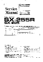
Service Manual (1D PIONEER® The Art of Entertainment ca. O tro 6 6- o f-2 0.6:0 STEREO RECEIVER SX-255R SX-205 THIS MANUAL IS APPLICABLE TO THE FOLLOWING MODEL(S) AND TYPE(S). Type Model SX-255R SX-205 Power Requirement The voltage can be converted by the following method. KUXJ 0 0 - Pioneer SX-255R | Service Manual - Page 2
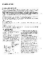
SX-255R, SX-205 1. SAFETY INFORMATION This service manual is intended for qualified service technicians; it is not meant for the casual do-it-yourselfer. Qualified technicians have the necessary test equipment and tools, and have been trained to properly and safely repair complex products such as - Pioneer SX-255R | Service Manual - Page 3
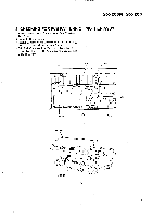
SX-255R, SX-205 2. CHECKING FOR PCB PATTERN OF MOTHER ASSY 1. Remove lower set screw at the center of the Chassis and Rear Panel. 2. Cut binder ® and remove. 3. - Pioneer SX-255R | Service Manual - Page 4
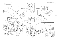
SX-255R/ Remote Control Unit (CU-SX108) AXD7085 NSP 58 Battery (R6P, AA) VEM-013 59 Loop Antenna ATB7004 60 FM Antenna ADH1017 16 Foot NSP 17 Binder 18 PCB Support 19 Mica Sheet 20 Strain Relief AEC1505 ZCA-BK1 AEC1581 AEE1014 CM-22C 61 Battery Cover AZA7123 62 63 Operating Instructions - Pioneer SX-255R | Service Manual - Page 5
- 205/ KUXJ, SDXJ only' 28 29 7 - -1 SX-255R/ LE_5-- L!-__-_-52_J'YPWXJ only 43 SX-255R/KUXJ, KCXJ, YPWXJ only Except SX-255R/YPWXJ 7 SX- 255R/ KUXJ, KCXJ and SX- 205/ KUXJ only 50 O 18 45 17 38 54 22 Except SX-255R/YPWXJ 39 I 16 L _ 56 52 SX- 255R/ YPWXJ only o Qd 26 I---- 47 22 oHc - Pioneer SX-255R | Service Manual - Page 6
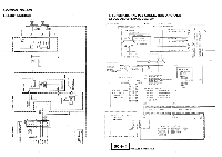
O O0 SX-205/SDXJ ONLY SX-255R/KUXJ.KCXJ SX-205/XUXJ AC120y 60H. SX-255R/YPWXJ AC240V 50H. NEUTRAL AKF-11 \\ BLUE E] SX-205/SOXJ LIVE = BROWN AC110/120-127/230/240V 50/60H. AC POWER CORD (P001015:5X-255R/KUXa KCXJ SX-205/KUXJ) AKE-116- (A001159,SX-255R/YPWXJ) (ADG1157.SX-205./SOXJ - Pioneer SX-255R | Service Manual - Page 7
S832 BAND S833 PHONO S834 TAPE 2 S835 TAPE 1NCR S836 S. BASS S837 MEMORY S838 CD S839 LD/DVD S840 TUNER POWER SW. Assy S876 POWER STANDBY/ON (for SX-255R) S401 POWER (for SX-205) SP SW. AND HP. Assy S701 SPEAKER A ON/OFF S702 SPEAKER B ON/OFF OVERALL SCHEMATIC DIAGRAM SCH -1 9 D1SA1 2-150-2651 - Pioneer SX-255R | Service Manual - Page 8
unless otherwise noted. Value in( ) is DC voltage at rated power. 1.Op MIX AMP 01 02 2SC2223 11.5 (FM) 5112 100 T101 ATE-063 IF OUT (FM GNDY 8 Stereo Distortion Adjustment GND 29- 1 M O ta C5.4 0 - Pioneer SX-255R | Service Manual - Page 9
C1- N 777 GND (FM) 77 GND Oa lI 0 N.,,,, SX-255R/KUXJ. KCXJ SX-205/KUXJ R156 R157 R163 R164 R159 R160 C165 C166 1 . OK GND in ,t) xt Lp STEREO .51 TUNED ,sATU . MUTE GND1 (FM) a (FM)c 5 C1 91 R193 4 . 7/50 220 i W. N crt Y av- ('-•' GND GND tio, s U. CU *5 GND \ m l0 - Pioneer SX-255R | Service Manual - Page 10
/50 0226 ,1„. 8 R208 R210 \ 5. MTZJ POWER AMP 6347 1,.L 0 A KPE9 305 220 03j1 RAA MUTE 0 FUNC DA U (f) Z A < L(1 IL -2 FUNC CK PUNE ST a STEREO a PLL CE O PLL DA F- PLL CK 0 0.0ND A.MLITE ss SX-255R SX-206/SOXJ) MWZ840 2 t SX-255R/YPW)(0) CN901 AKE7021 0 P 540 54- 549 o SPEAKERS - Pioneer SX-255R | Service Manual - Page 11
577.0" 6- V•1250 0 91.1A° '851 2gid C...) 02 00 PCB SUPPORT 1631I! C '8 (30C) 0 , O A439_ 0,Rv33,-800 E Oa 00 I0 .0 ,0 120 101 c) ,0 SR UT 4°7 1__/ . 9323 My tEL AEC REC POWER CT ( 7.2558 ONLY O 111 o , 40,10V • • 0000009.2jj KPD1 010 Fig. FIB check with the schematic diagram. • - Pioneer SX-255R | Service Manual - Page 12
SUPPORT P3X 8378 To POWER TRANSFORMER PRIMARY Assy SX-255R, SX-205 PCB POWER CORD NOTE FOR PCB DIAGRAMS: 1. Part numbers In PCB diagrams match those in the schematic diagrams. 2. A comparison between the main parts ol PCB and schematic diagrams is shown below. Symbol in PCB Symbol in Schematic - Pioneer SX-255R | Service Manual - Page 13
wi thout vol tape Is GOY M CCMA NP,CEANP TY:OFTXA SIGNAL ROUTE 010,, AUD10 SIGNAL ROUTE SCH 5 18 VOL. ASSY POWER SW. Assy (for SX-255R) RWZ8094 0 0875 O STANDBY ,,975 IND C"^x", POWER 5871 as STANDBY IND 0. END K13 KO2 • This diagram is viewed from the mounted parts side. The parts mounted on - Pioneer SX-255R | Service Manual - Page 14
SW. Assy (for SX-255R) PWZ8094 O 0876 O STANIDNBCY CRI-N87N5-C POWER SW 587E STANDBDY. AINNDD KI3 KO2 • This diagram is viewed from the mounted parts side. I The parts mounted on this PCB include all necessary parts - Pioneer SX-255R | Service Manual - Page 15
DA PLL CK VOL UP SQ'- VOL DOWN MUTE 0828 DTA14 ES -T DC.DETECT W r W MUTE g m= , o w 0 ty '- c.) 0.L.DET ID REMOTE - CONTROL SIGNAL BUFFER 0829 DTA143ES * vou 801 GP1 058X Vcc m1o›- GN0 G G G f,L 0830 DTC143ES RESET C831 2.2/50 SX-20 UXJ, SDXJ ONLY R862 mfr.4_ V 0 47k - Pioneer SX-255R | Service Manual - Page 16
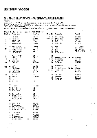
List for SX-255R/KUXJ Mark VOL. ASSY -POWER SW. ASSY SPEAKER TERMINAL 8-P JACK/12V CRYSTAL RESONATOR CRYSTAL RESONATOR FM/AM TUNER FE MODULE AKE7021 PKN1004 ASS1042 ASS1066 AXQ1002 Note: FMIAM. TUNER FE MODULE has no service part. FL AND UCOM ASSY SEMICONDUCTORS I0501 IC826 OP-AMP IC CONTROL - Pioneer SX-255R | Service Manual - Page 17
SX-255R, SX REMOTE RECEIVER UNIT FL TUBE CERAMIC RESONATOR (7.7MHz) GP1U58X AAV7026 ASS1055 VOL. ASSY SEMICONDUCTORS IC601 Q612, Q613 Q614, Q615 Q631, Q632 OP-AMP KPE12 Mark No. Description Parts No. POWER SW. ASSY SEMICONDUCTOR D876 RED LED service part. BARRIER ASSY BARRIER Assy has no - Pioneer SX-255R | Service Manual - Page 18
SX-255R, SX-205 7. ADJUSTMENTS ADJUSTMENT OF FM TUNER SECTION • Set the FM/AM selector to FM BAND. • Connect the wiring as shown in Fig. 1-1. Step No. Adjustment Title Center 1 Adjustment Front End 2 Sencitivity Check Stereo 3 Distortion Check Stereo Location Specifications TUNED - Pioneer SX-255R | Service Manual - Page 19
SX-255R, SX-205 60cm Loop antenna AM SG MPX SG Center Center AM antenna terminal FM SG PRODUCT .41 FM 75 fl antenna terminal Fig. 1-1 FM and - Pioneer SX-255R | Service Manual - Page 20
SX-255R, SX-205 8. IC INFORMATION • The information shown in the list is basic information and may not correspond exactly to that shown in the schematic diagrams. • PDG172A (IC826: FL AND UCOM ASSY) • Receiver Control Micro-computer • Block Diagram ANO to ANT I 8 TO to TT , 0 TVS 28 y• 8 115/S 2t - Pioneer SX-255R | Service Manual - Page 21
analog input terminal 30 RST I/O " L " level active system reset terminal. The RST terminals are I/O terminals, and at the time of power supply start-up, the built-in power ON reset function operates and executes " L " level output. (Mask option) 31 EXTAL 32 XTAL I System clock oscillstion - Pioneer SX-255R | Service Manual - Page 22
SX-255R, SX-205 9. FL INFORMATION ■ AAV7026 (V826: FL AND UCOM ASSY) • FL Tube • Grid Assignment 1G BO ED-IIILMONESSS.BASS P-10 ON OFF 000° SE, DoDoO 41G I 5G 616 2IG TAPEZ MSS> 2 3 STEREO MED 0.00 IHIKO WANT 0° 0° II 0°0° EMORY RDS ph Dig OR' OK IL--=EOM ER1 16boa Cell O 0 0 S6 - Pioneer SX-255R | Service Manual - Page 23
Assy 38 MOTHER Assy 39 FL AND UCOM Assy 43 VOL. Assy 44 POWER SW. Assy 41 TRANS Assy NSP 46 PRIMARY Assy NSP 47 BARRIER Assy SX-255R/ KUXJ SX-255R/ KCXJ Part No. SX-255R/ YPWXJ SX-205/ KUXJ AWK7254 AWZ8086 AWZ8090 AWZ8092 AWZ8094 AWZ8097 AWZ8369 AWZ8371 AWK7254 AWZ8086 AWZ8090 - Pioneer SX-255R | Service Manual - Page 24
SX-255R1 SX-255R/ KUXJ KCXJ Part No. SX-255R/ YPWXJ SX-205/ KUXJ SX-205/ SDXJ Remarks NSP NSP 68 Packing Case AHD7265 57 Remote Control Unit (CU-SX108) AXD7085 61 Battery Cover AZA7123 58 Battery (R6P, AA) VEM-013 63 Operating Instructions (English) ARB7064 Operating Instructions - Pioneer SX-255R | Service Manual - Page 25
SX-255R, SX-205 MOTHER Assy AWZ8087, AWZ8088, AWZ8089 and AWZ8086 have the same construction Used PKN1004 AICF1060 Not Used AK1D1060 Not Used Note *2. Refer to " 5. SCHEMATIC AND PCB CONNECTION DIAGRAMS". POWER SW. Assy AWZ8095 and AWZ8094 have the same construction except for the following: - Pioneer SX-255R | Service Manual - Page 26
Antenna 1 Operating Instructions 1 [SX-255R1 Remote control unit 1 Dry cell batteries (size "AA" (R6P)) 2 Measuredpursuant to the Federal Trade Commission's Trade Regulation rule on Power Output Claims for Amplifiers. ** Measured By Audio Spectrum Analyzer. NOTE: Specifications and - Pioneer SX-255R | Service Manual - Page 27
output jacks of a compact disc player. ® CONTROL OUT jacks (SX-255R only) Connect this jack to other Pioneer components bearing the gill mark when using the remote control of this unit to control the other components. CONTROL (oTrr Receiver Pioneer component bearing the El mark. Remote control - Pioneer SX-255R | Service Manual - Page 28
. • The accessory remote control unit can also be used to operate STANDBY/ON. NOTE: When the power is initially turned ON, muting will be applied to prevent sound from being output for approx. 5 seconds. ® POWER switch/POWER indicator (SX-205) When this switch is pressed, power is supplied to the - Pioneer SX-255R | Service Manual - Page 29
. In this event, setting the receiver to the monaural mode will reduce the noise. In this case, however, FM stereo broadcasts will be reproduced in monaural sound. NOTE: This button has no effect on reception of AM broadcasts. to Remote sensor window (SX-255R) CLASS button Use to switch between
-
 1
1 -
 2
2 -
 3
3 -
 4
4 -
 5
5 -
 6
6 -
 7
7 -
8
-
9
-
10
-
11
-
12
-
13
-
14
-
15
-
16
-
17
-
18
-
19
-
20
-
21
-
22
-
23
-
24
-
25
-
26
-
27
-
28
-
29
 |
 |
Service
Manual
STEREO
RECEIVER
SX-255R
SX-205
(1D
PIONEER®
The
Art
of
Entertainment
.
caO
6
-
6
tro
o
-
f2
0.6:0
THIS
MANUAL
IS
APPLICABLE
TO
THE
FOLLOWING
MODEL(S)
AND
TYPE(S).
Type
Model
Power
Requirement
The
voltage
can
be
converted
by
the
following
method.
SX-255R
SX-205
KUXJ
0
0
AC120V
KCXJ
0
-
AC120V
SDXJ
-
0
AC110V/120-127V/230V/240V
With
the
voltage
selector
YPWXJ
0
—
AC240V
CONTENTS
1.
SAFETY
INFORMATION
2
6.
PCB
PARTS
LIST
23
2.
CHECKING
FOR
PCB
PATTERN
OF
7.
ADJUSTMENTS
26
MOTHER
ASSY
3
8.
IC
INFORMATION
28
3.
EXPLODED
VIEWS,
PACKING
AND
9.
FL
INFORMATION
30
PARTS
LIST
4
10.
FOR
SX-255R/KCXJ,
YPWXJ,
SX-205/KUXJ
4.
BLOCK
DIAGRAM
7
AND
SDXJ
31
5.
SCHEMATIC
AND
PCB
CONNECTION
11.
SPECIFICATIONS
34
DIAGRAMS
8
12.
PANEL
FACILITIES
35
PIONEER
ELECTRONIC
CORPORATION
4-1,
Meguro
1-Chome,
Meguro-ku, Tokyo
153,
Japan
PIONEER
ELECTRONICS
SERVICE
INC.
P.O.
Box
1760,
Long
Beach,
CA
90801-1760,
U.S.A.
PIONEER
ELECTRONIC
[EUROPE]
N.V
.
Haven
1087
Keetberglaan
1,
9120
Melsele,
Belgium
PIONEER
ELECTRONICS
ASIACENTRE
PTE.
LTD.
501
Orchard
Road,
#10-00
Lane
Crawford
Place,
Singapore
0923
CD
PIONEER
ELECTRONIC
CORPORATION
1996
O-DFG
JAN.
1996
Printed
in
Japan