Pioneer SX-255R Service Manual - Page 18
Sx-255r, Sx-205, Adjustments
 |
View all Pioneer SX-255R manuals
Add to My Manuals
Save this manual to your list of manuals |
Page 18 highlights
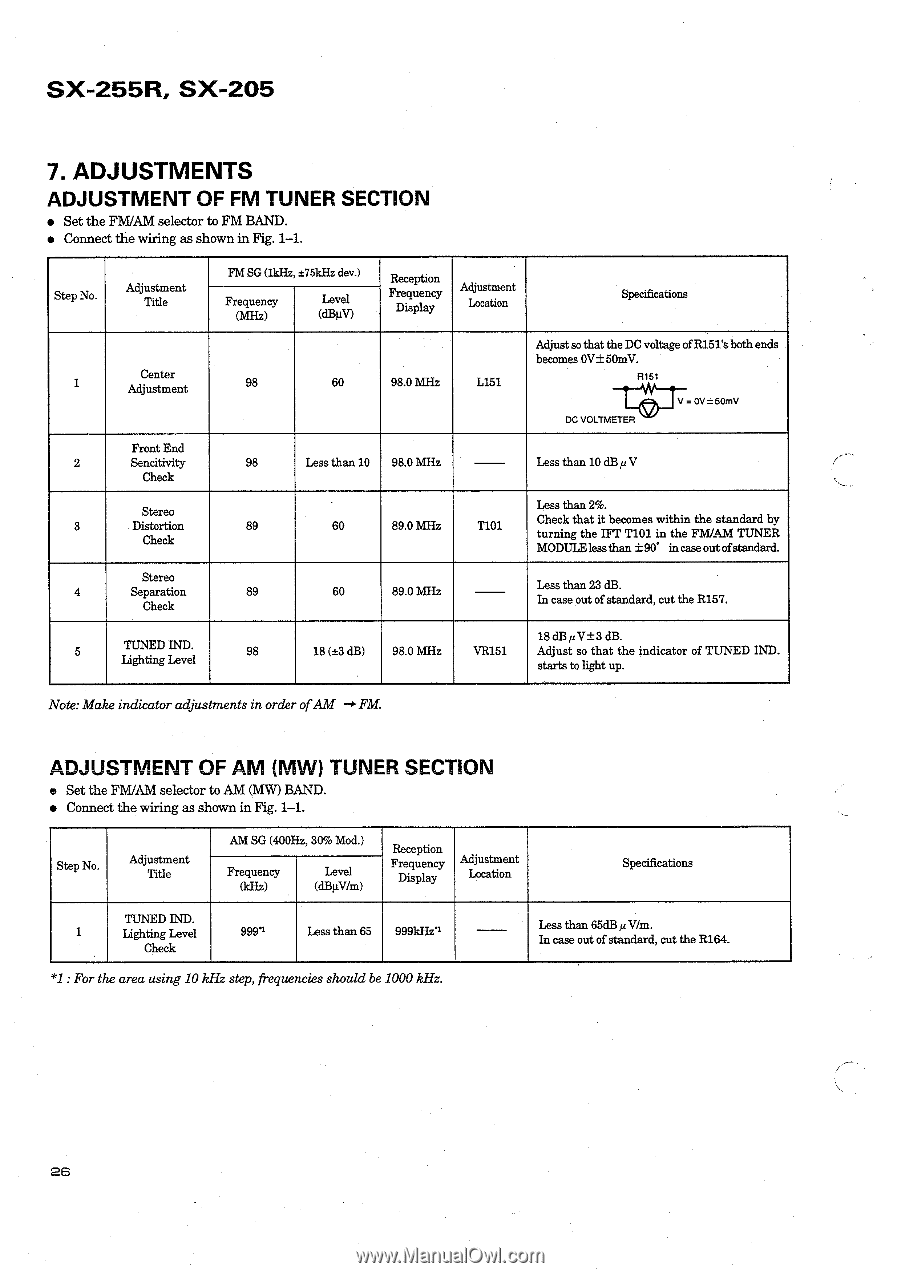
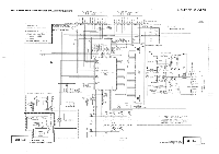
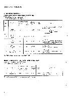
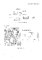
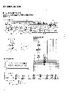
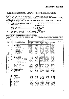
SX-255R, SX-205 7. ADJUSTMENTS ADJUSTMENT OF FM TUNER SECTION • Set the FM/AM selector to FM BAND. • Connect the wiring as shown in Fig. 1-1. Step No. Adjustment Title Center 1 Adjustment Front End 2 Sencitivity Check Stereo 3 Distortion Check Stereo 4 Separation Check 5 TUNED IND. Lighting Level FM SG (1kHz, ±75kHz dev.) Frequency (MHz) Level (dBµV) 98 60 Reception Frequency Adjustment Display Location Specifications 98.0 MHz L151 Adjust so that the DC voltage of R151's both ends becomes OV±50mV. R151 DC VOLTMETER = ov ±50mV 98 Less than 10 98.0 MHz Less than 10 dBit V Less than 2%. 89 60 89.0 MHz T101 Check that it becomes within the standard by turning the IFT T101 in the FM/AM TUNER MODULE lessthan ±90° in race out ofstandard. 89 60 89.0 MHz Less than 23 dB. In case out of standard, cut the R157. 18 dB 12 V±3 dB. 98 18 (±3 dB) 98.0 MHz VR151 Adjust so that the indicator of TUNED IND. starts to light up. Note: Make indicator adjustments in order of AM -0 FM. ADJUSTMENT OF AM (MW) TUNER SECTION • Set the FM/AM selector to AM (MW) BAND. • Connect the wiring as shown in Fig. 1-1. Step No. Adjustment Title AM SG (400Hz, 30% Mod.) Frequency (kHz) Level (dBµV/m) Reception Frequency Adjustment Display Location Specifications TUNED IND. 1 Lighting Level Check 999"' Less than 65 999kHei Less than 65dB y Wm. In case out of standard, cut the R164. *1 : For the area using 10 kHz step, frequencies should be 1000 kHz. 26
-
 1
1 -
2
-
3
-
4
-
5
-
6
-
7
-
8
-
9
-
10
-
11
-
12
-
 13
13 -
 14
14 -
 15
15 -
 16
16 -
 17
17 -
 18
18 -
 19
19 -
 20
20 -
 21
21 -
 22
22 -
 23
23 -
24
-
25
-
26
-
27
-
28
-
29
 |
 |