Pioneer VSX-21 Operating Instructions - Page 10
Video Components Connections
 |
UPC - 012562957067
View all Pioneer VSX-21 manuals
Add to My Manuals
Save this manual to your list of manuals |
Page 10 highlights
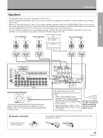
Connections Video Components Connections • When connecting components, the receiver should be off and the power cord unpluged. • Connect your video components as shown below. Also, refer to "Digital Connections" on page 11 when making digital connections from your DVD or LD player. • Although only "S2" is printed on the S-Video jacks on the rear panel, S, S1 and S2 S-video connection can be made as well. • If your TV monitor or video camera has an S-Video input, clearer picture reproduction is possible by connecting the receiver to your TV monitor or video camera via the S-Video jack. TV monitor INPUT VIDEO S-VIDEO » Video deck (1) « OUTPUT INPUT V V L L R R » Video deck (2) OUTPUT INPUT V V L L R R « » ANTENNA DIGITAL IN OPT 1 PCM/ /DTS FM UNBAL 75Ω OPT 2 OPT 3 DVD 5.1 CH INPUT SURROUND L SUBWOOFER AM LOOP ANTENNA S2 TO OUT MONITOR TV OPT DIGITAL OUT COAX R IN L PCM/ /DTS DIGITAL IN R CENTER OUT PLAY REC MD/TAPE 1 CONTROL OUT IN VIDEO OUT IN IN OUT PLAY REC CD TAPE 2 MONITOR IN IN IN OUT S2 S2 S2 S2 IN IN IN OUT IN IN IN OUT TV/ SAT DVD/ LD DVD 5.1 CH FRONT VCR 1 IN OUT S2 S2 VIDEO IN OUT IN OUT L R VCR 2 FRONT PREOUT L R FRONT SPEAKERS R L CENTER PREOUT L SORROUND PREOUT R SUBWOOFER PREOUT CENTER SPEAKER R L SURROUND SPEAKERS A B CAUTION: SEE INSTRUCTION MANUAL ATTENTION: SEE INSTRUCTION MANUAL 6~LESS THAN 8Ω /SPEAKER 6~MOINS DE 8Ω /HAUTPARLEUR 8~16Ω / SPEAKER 8~16Ω / SPEAKER IMPEDANCE SELECTOR AC OUTLET AC 120V 60Hz 7 Front VIDEO INPUT S-VIDEO VIDEO L AUDIO R Video camera (etc.) VIDEO INPUT L R » OUTPUT V L R TV tuner (or satellite tuner) » OUTPUT V L R DVD player (or LD player) memo When connecting components equipped with S-video jacks, you can make connections to this unit using S-video cords (not supplied). However, this unit is not designed to convert the format of the video signal. Therefore, the signal from the S2 IN cannot be output from the VIDEO OUT and similarly the signal from the VIDEO IN cannot be output from the S2 OUT. 10 7 Audio/Video cords Use audio/video cords (not supplied) to connect the video components and a video cord to connect the TV or monitor. VIDEO Connect red plugs to R (right), L white plugs to L (left), and the yellow plugs to VIDEO. Be sure to insert completely. R
-
 1
1 -
2
-
3
-
4
-
 5
5 -
 6
6 -
 7
7 -
 8
8 -
 9
9 -
 10
10 -
 11
11 -
 12
12 -
 13
13 -
 14
14 -
 15
15 -
16
-
17
-
18
-
19
-
20
-
21
-
22
-
23
-
24
-
25
-
26
-
27
-
28
-
29
-
30
-
31
-
32
-
33
-
34
-
35
-
36
-
37
-
38
-
39
-
40
-
41
-
42
-
43
-
44
-
45
-
46
-
47
-
48
-
49
-
50
-
51
-
52
-
53
-
54
-
55
-
56
-
57
-
58
-
59
-
60
 |
 |
