Poulan 1400T User Manual - Page 8
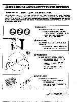
Shield, Awarning
 |
View all Poulan 1400T manuals
Add to My Manuals
Save this manual to your list of manuals |
Page 8 highlights
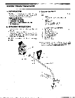
3.SHIELD- Finny 4 AWARNING Failureto install theshieldiMhe position shownin Figure 4and5can result inseriousinjurytothe operator. The length of theshield must bealigned with the length of the driveshaft housing.Direct thewidest partof theshield toward the engine. CAUTION: The Line Limiter is sharp and can cut you. a. Match the Key (Raised area) on the Shield with the Keyway ("V" slot) on the Drive Shaft Housing. Figure 4(Inset). b. Rest thebottomof the Shield ontopoftheshoulder located on the Drive Shaft Housing above the Dust Cup. NOTE: The bottom of the Shield must rest on top of the shoulder of the Drive Shaft Housing. c. Install theBracket and Screwsas shown in Figure4. d. Tighten the Screws evenly and securely with a wrench. NUIE: A small space may be left between the Bracket and the Shield when hardware is fully tightened. 4. ASSIST HANDLE -Figure 5 a. Hold the Assist Handle and with the hollow side facing the Enginesoit isaligned between theEngineand the Safety Label on the Drive Shaft Housing. Figure 5. b. Firmly push the Assist Handle over the Drive Shaft Housing. Figure 5. c. Install the Bolt in the side of the Assist Handle with the hex opening. d. Install the Washer and Wing Nut. Figure 5. e. Tighten the Wing Nut by hand on/: 4.0PERATiNG POSITION - Figure 6 a. Before starting the Engine, stand as shown in Figure 6 and check for the following: D. Left arm fully extended, hand holding Assist Handle. 2). Right arm slightly bent, hand holding the Rear Handle, and fingers on Throttle Trigger. 3). Rear Handle below waist level. 4). Weight of tool evenly distributed between arms. 5). Without operator bending, the Trimmer Head is near and parallel to the ground and easily contacts the material to be cut. b. Adjust the Assist Handle up or down the Drive Shaft Housing (but above the Safety Label) to a comfortable position. 1). Loosen the Wing Nut by hand, adjust the Assist Handle. Retighten Wing Nut by hand only: 2). Rotate the Assist Handle from leftto right if it is necessary to tilt the angle of the Trimmer Head when cutting a large, sloped area such as a ditch bank. sttWitiltS1 WIDEST PART OF SHIELD RAISED AREA BOTTOM OF SHIELD "V"SLOIT SHOULDER DUST CUP KEYWAY KEY // SCREW S. t BRACKET HARDWARE SHOWN ACTUAL SIZE Figure 4 HARDWARE SHOWN ACTUAL. SIZE WING NUT Zt v WASHER BOLT SAFETY LABELS Figure 5 RIGHT ARM SLIGHTLY BENT. HAND HOLDING REAR HANDLE, FINGERS ON THROTTLE r TRIGGER / ••• SAFETY FACE SHIELD REAR HANDLE BELOW WAIST LEVEL 1A.......LEFT ARM EXTENDED. HAND HOLDING ASSIST HANDLE TRIMMER HEAD IS NEAR THE GROUND AND EASILY CONTACTS MATERIAL TOBE CUT Figure 6
-
 1
1 -
2
-
 3
3 -
 4
4 -
 5
5 -
 6
6 -
 7
7 -
 8
8 -
 9
9 -
 10
10 -
 11
11 -
 12
12 -
 13
13 -
14
-
15
-
16
-
17
-
18
-
19
-
20
 |
 |
