Poulan PR28PS Instruction Manual - Page 17
Poulan PR28PS Manual
 |
View all Poulan PR28PS manuals
Add to My Manuals
Save this manual to your list of manuals |
Page 17 highlights
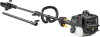
2. OPERATING THE COUPLER Pull starter rope handle until engine starts. If the unit still does not start, refer to TROUBLESHOOTING TABLE or call customer support. Coupler Primary Hole Guide Recess This model is equipped with a coupler which enables optional attachments to be installed. The optional attachments are: MODEL: Edger ...PP1000E Cultivator ...PP2000T Blower ...PP3000B Brushcutter ...PP4000C Pruner ...PP5000P Pruner ...PP5500P Hedge Trimmer ...PP6000H Upper Shaft Locking/ Release Attachment Button tachments, place the unit on a flat surface for stability. 1. Loosen the coupler by turning the knob counterclockwise. Coupler Locking/Release Button in Primary Hole Attachment LOOSEN REMOVING ATTACHMENTS CAUTION: When removing or installing at- WARNING: Always stop unit and disconnect spark plug before removing or installing attachments. WARNING: Make sure the locking/ release button is locked in the primary hole and the knob is securely tightened before operating the unit. All attachments are designed to be used in the primary hole unless otherwise stated in the applicable attachment instruction manual. Using the wrong hole could lead to serious injury or damage to the unit. INSTALLING ATTACHMENT HANGER Knob TIGHTEN 2. Press and hold the locking/release button. Locking/Release Button An attachment hanger is provided for storage when attachment is not in use. To install hanger on attachment: 1. Remove the shaft cap from the attachment (if present) and discard. 2. Press and hold the locking/release button. 3. Push hanger onto the attachment until the locking/release button snaps into the hole. Upper Shaft Attachment Coupler 3. While securely holding the engine end shaft and extension shaft, pull the attachment straight out of the extension shaft coupler. 4. Repeat steps to remove extension shaft from coupler on engine end shaft. INSTALLING OPTIONAL ATTACHMENTS 1. Remove the shaft cap from the attachment (if present). 2. Position locking/release button of attachment into guide recess of coupler on engine end shaft. 3. Push the attachment into the coupler until the locking/release button snaps into the primary hole. 4. Before using the unit, tighten the knob securely by turning clockwise. 17
-
 1
1 -
2
-
3
-
4
-
5
-
6
-
7
-
8
-
9
-
10
-
11
-
 12
12 -
 13
13 -
 14
14 -
 15
15 -
 16
16 -
 17
17 -
 18
18 -
 19
19 -
 20
20 -
 21
21 -
 22
22 -
23
-
24
-
25
-
26
-
27
-
28
-
29
-
30
-
31
-
32
-
33
-
34
-
35
-
36
-
37
-
38
-
39
-
40
-
41
-
42
-
43
-
44
-
45
-
46
-
47
-
48
-
49
-
50
-
51
-
52
-
53
-
54
-
55
-
56
-
57
-
58
-
59
-
60
-
61
-
62
-
63
-
64
-
65
-
66
-
67
-
68
-
69
-
70
-
71
-
72
-
73
-
74
-
75
-
76
-
77
-
78
-
79
-
80
-
81
-
82
-
83
-
84
-
85
-
86
-
87
-
88
-
89
-
90
-
91
-
92
-
93
-
94
-
95
-
96
-
97
-
98
-
99
-
100
 |
 |