Poulan PR28PS Instruction Manual - Page 9
Poulan PR28PS Manual
 |
View all Poulan PR28PS manuals
Add to My Manuals
Save this manual to your list of manuals |
Page 9 highlights
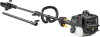
ASSEMBLY (PRUNER ATTACHMENT) CAUTION: If received assembled, repeat all steps to ensure your unit is properly assembled and all fasteners are secure. Examine parts for damage. Do not use damaged parts. NOTE: If you need assistance or find parts missing or damaged, call 1-800-554-6723. It is normal for the fuel filter to rattle in the empty fuel tank. Finding fuel or oil residue on muffler is normal due to carburetor adjustments and testing done by the manufacturer. TOOLS REQUIRED S Hex wrench (provided) NOTE: DO NOT use pruner extension shaft with other attachments. 7. Before using the unit, tighten both knobs securely by turning clockwise. WARNING: Make sure the locking/ release button is locked in the primary hole of both couplers and the knobs are securely tightened before operating the unit. Using the wrong holes could lead to serious injury or damage to the unit. tachments, place the unit on a flat surface for stability. NOTE: The pruner attachment connects to the engine end shaft through use of a coupler system. For extra reach, the extension shaft (included) can be used. 1. Loosen the couplers on the extension shaft and on the engine end shaft by turning the knobs counterclockwise. Coupler Shipping protector INSTALLING PRUNER ATTACHMENT CAUTION: When removing or installing at- Locking/Release Button in Primary Hole For assembly of optional attachments, refer to the ASSEMBLY section of the applicable attachment instruction manual. SHOULDER STRAP ASSEMBLY LOOSEN Knob TIGHTEN 2. Remove shipping protector from coupler. 3. Remove the shaft cap from the pruner attachment (if present). 4. Position locking/release button of attachment into guide recess of coupler on extension shaft. 5. Push the attachment into the coupler until the locking/release button snaps into the primary hole. Coupler Primary Hole Guide Recess WARNING: Proper shoulder strap adjustments must be made with the engine completely stopped before using unit. 1. Try on shoulder strap and adjust for fit and balance before starting the engine or beginning a cutting operation. 2. Insert your right arm and head through the shoulder strap and allow it to rest on your left shoulder. Make sure the danger sign is centered on your back and the hook is to the right side of your waist. NOTE: A one-half twist is built in the shoulder strap to allow the strap to rest flat on the shoulder. 3. Adjust the strap, allowing the hook to be about 3 - 6 inches (8 - 15 cm) below the waist. 4. Fasten the strap hook to the clamp located between the throttle handle and the assist handle and lift the tool to the operating position. NOTE: It may be necessary to relocate the shoulder strap clamp on the shaft for proper balancing of unit. 1. Loosen and remove both clamp screws. 2. Place the upper shoulder strap clamp over the upper shaft. Locking/ Release Attachment Button 6. Repeat steps to attach extension shaft to coupler on engine end shaft. Upper Shaft TO RELOCATE SHOULDER STRAP CLAMP: 9
-
 1
1 -
2
-
3
-
 4
4 -
 5
5 -
 6
6 -
 7
7 -
 8
8 -
 9
9 -
 10
10 -
 11
11 -
 12
12 -
 13
13 -
 14
14 -
15
-
16
-
17
-
18
-
19
-
20
-
21
-
22
-
23
-
24
-
25
-
26
-
27
-
28
-
29
-
30
-
31
-
32
-
33
-
34
-
35
-
36
-
37
-
38
-
39
-
40
-
41
-
42
-
43
-
44
-
45
-
46
-
47
-
48
-
49
-
50
-
51
-
52
-
53
-
54
-
55
-
56
-
57
-
58
-
59
-
60
-
61
-
62
-
63
-
64
-
65
-
66
-
67
-
68
-
69
-
70
-
71
-
72
-
73
-
74
-
75
-
76
-
77
-
78
-
79
-
80
-
81
-
82
-
83
-
84
-
85
-
86
-
87
-
88
-
89
-
90
-
91
-
92
-
93
-
94
-
95
-
96
-
97
-
98
-
99
-
100
 |
 |