ProForm 280 Razor Instruction Manual - Page 8
Attach the Right Pulse Bar 16 to
 |
View all ProForm 280 Razor manuals
Add to My Manuals
Save this manual to your list of manuals |
Page 8 highlights
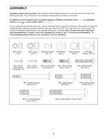
5. Identify the Left and Right Pulse Bars (5, 16), 5 which are marked with "Left" and "Right" stick- ers. Have another person hold the Right Pulse Bar (16) near the Console Bracket (3). Locate the wire tie in the Console Bracket (3). Tie the lower end of the wire tie to the right Pulse Wire (37). Next, pull the upper end of the wire tie upward out of the top of the Console Bracket. Then, untie and discard the wire tie. Repeat this step for the Left Pulse Bar (5). Wire Tie 37 5 86 Wire Tie 3 37 16 6. Slide the Right Pulse Bar (16) onto the right side of the Console Bracket (3). Make sure that the hexagonal holes are in the indicated location. Tip: Avoid pinching the wires during this step. Attach the Right Pulse Bar (16) to the Console Bracket (3) with two M8 x 38mm Button Bolts (98) and two M8 Locknuts (82). Make sure that the Locknuts are in the hexagonal holes. Repeat this step for the Left Pulse Bar (5). 6 37 5 86 Avoid pinching the wires 3 98 37 16 82 Hexagonal Holes 7. The Console (4) can use four AA batteries (not 7 included); alkaline batteries are recommended. IMPORTANT: If the Console has been exposed to cold temperatures, allow it to warm to room temperature before inserting batteries. Otherwise, you may damage the console displays or other electronic compo- nents. Remove the screw, remove the battery 4 cover, insert the batteries into the battery com- partment, and then reattach the battery cover. Make sure to orient the batteries as shown by the diagram inside the battery compart- ment. Screw Cover Batteries 8
-
 1
1 -
2
-
 3
3 -
 4
4 -
 5
5 -
 6
6 -
 7
7 -
 8
8 -
 9
9 -
 10
10 -
 11
11 -
 12
12 -
 13
13 -
14
-
15
-
16
-
17
-
18
-
19
-
20
-
21
-
22
-
23
-
24
-
25
-
26
-
27
-
28
 |
 |
