ProForm 475 E Elliptical English Manual - Page 19
Upper Body Leg 5 and the Right Pedal Arm 9. Then
 |
View all ProForm 475 E Elliptical manuals
Add to My Manuals
Save this manual to your list of manuals |
Page 19 highlights
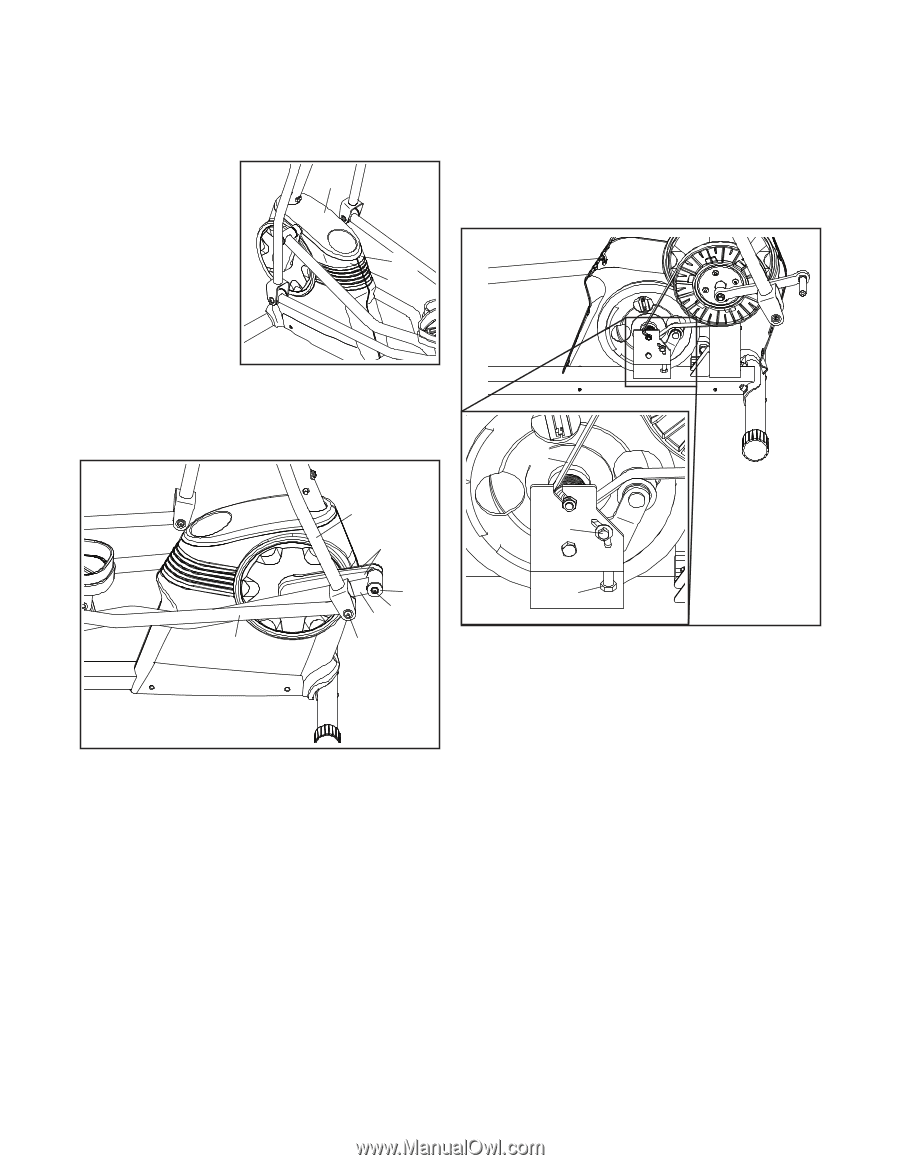
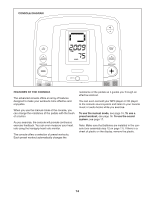
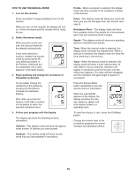
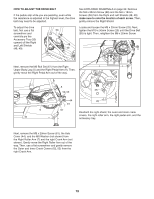
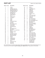
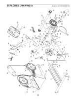
HOW TO ADJUST THE DRIVE BELT If the pedals slip while you are pedaling, even while the resistance is adjusted to the highest level, the drive belt may need to be adjusted. See EXPLODED DRAWING A on page 22. Remove the M4 x 25mm Screw (68) and the M4 x 16mm Screws (56) from the Right and Left Shields (48, 49); make sure to note the location of each screw. Then, gently remove the Right Shield. To adjust the drive belt, first use a flat screwdriver and carefully pry the Accessory Tray (50) upward off the Right and Left Shields (48, 49). Locate and loosen the M6 x 20mm Screw (25). Next, 50 tighten the M10 x 50mm Screw (20) until the Drive Belt (55) is tight. Then, retighten the M6 x 20mm Screw. 48 49 Next, remove the M6 Bolt Set (67) from the Right Upper Body Leg (5) and the Right Pedal Arm (9). Then, gently move the Right Pedal Arm out of the way. 55 5 25 52, 53 44 20 7 61 9 67 Reattach the right shield, the outer and inner crank covers, the right roller arm, the right pedal arm, and the accessory tray. Next, remove the M8 x 20mm Screw (61), the Axle Cover (44), and the M8 Washer (not shown) from the Right Roller Arm (7) and the right Crank Arm (not shown). Gently move the Right Roller Arm out of the way. Then, use a flat screwdriver and gently remove the Outer and Inner Crank Covers (52, 53) from the right Crank Arm. 19
-
 1
1 -
2
-
3
-
4
-
5
-
6
-
7
-
8
-
9
-
10
-
11
-
12
-
13
-
 14
14 -
 15
15 -
 16
16 -
 17
17 -
 18
18 -
 19
19 -
 20
20 -
 21
21 -
 22
22 -
 23
23 -
 24
24
 |
 |