ProForm 625 Treadmill User Manual - Page 23
Part Identification Chart - user manual
 |
View all ProForm 625 Treadmill manuals
Add to My Manuals
Save this manual to your list of manuals |
Page 23 highlights
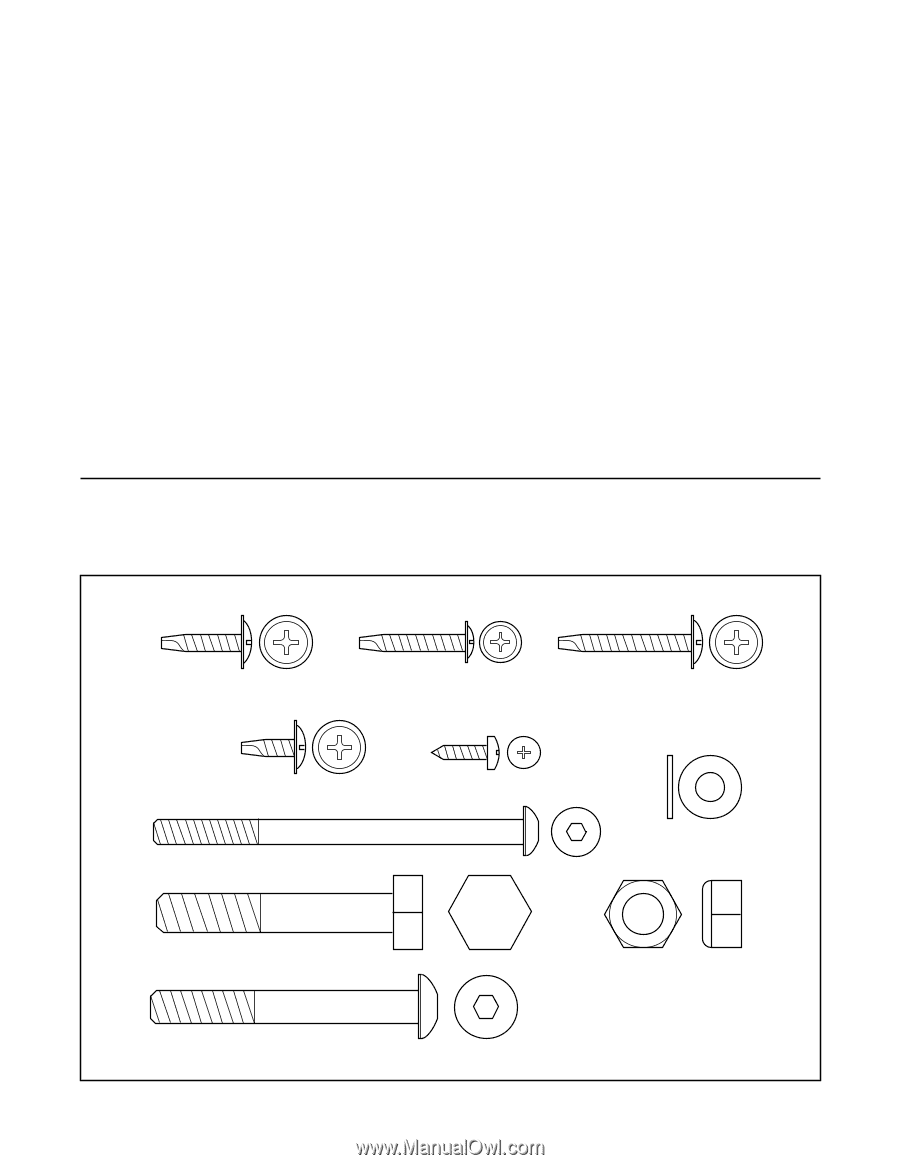
Key No. Qty. 103 4 104 2 105 1 106 1 107 2 108 4 109 1 110 1 111 1 112 1 113 1 114* 2 115 1 116 1 117 2 118 2 119 2 Description U-nut Base Endcap Shock Choke 3 1/2" Bolt 1" Tek Screw Pulse Bar Left Foam Grip Trim Guard Shield Small Bolt Extension Leg Assembly Base Console Base Bottom Upright Cap Incline Motor Spacer Base Pad Key No. Qty. Description 120 1 Right Frame Guide 121 1 Pulse Wire 122 1 Left Upright 123 4 Upright Washer 124 4 2 1/2" Bolt #1 8" White Wire, 2F #1 4" White Wire, M/F #1 8" Blue Wire, 2F #1 4" Blue Wire, 2F #1 4" Black Wire, 2F #1 12" Green Wire, F/Ring #1 4" Green Wire, F/Ring #1 8" Green Wire, 2 Ring #1 4" Red Wire, M/F #1 User's Manual # These parts are not illustrated * Includes all parts shown in the box PART IDENTIFICATION CHART Use the drawings below to identify small parts used during the assembly process (see pages 6-9). 3/4" Tek Screw (101)-2 1" Tek Screw (108)-4 1 1/4" Tek Screw (79)-4 1/2" Tek Screw (76)-8 1/2" Screw (46)-7 3 1/2" Bolt (107)-2 Washer (123)-4 Wheel Bolt (86)-2 2 1/2" Bolt (124)-4 23 Wheel Nut (15)-2
-
 1
1 -
2
-
3
-
4
-
5
-
6
-
7
-
8
-
9
-
10
-
11
-
12
-
13
-
14
-
15
-
16
-
17
-
 18
18 -
 19
19 -
 20
20 -
 21
21 -
 22
22 -
 23
23 -
 24
24 -
 25
25 -
 26
26
 |
 |