ProForm 625 Treadmill User Manual - Page 6
Assembly - parts
 |
View all ProForm 625 Treadmill manuals
Add to My Manuals
Save this manual to your list of manuals |
Page 6 highlights
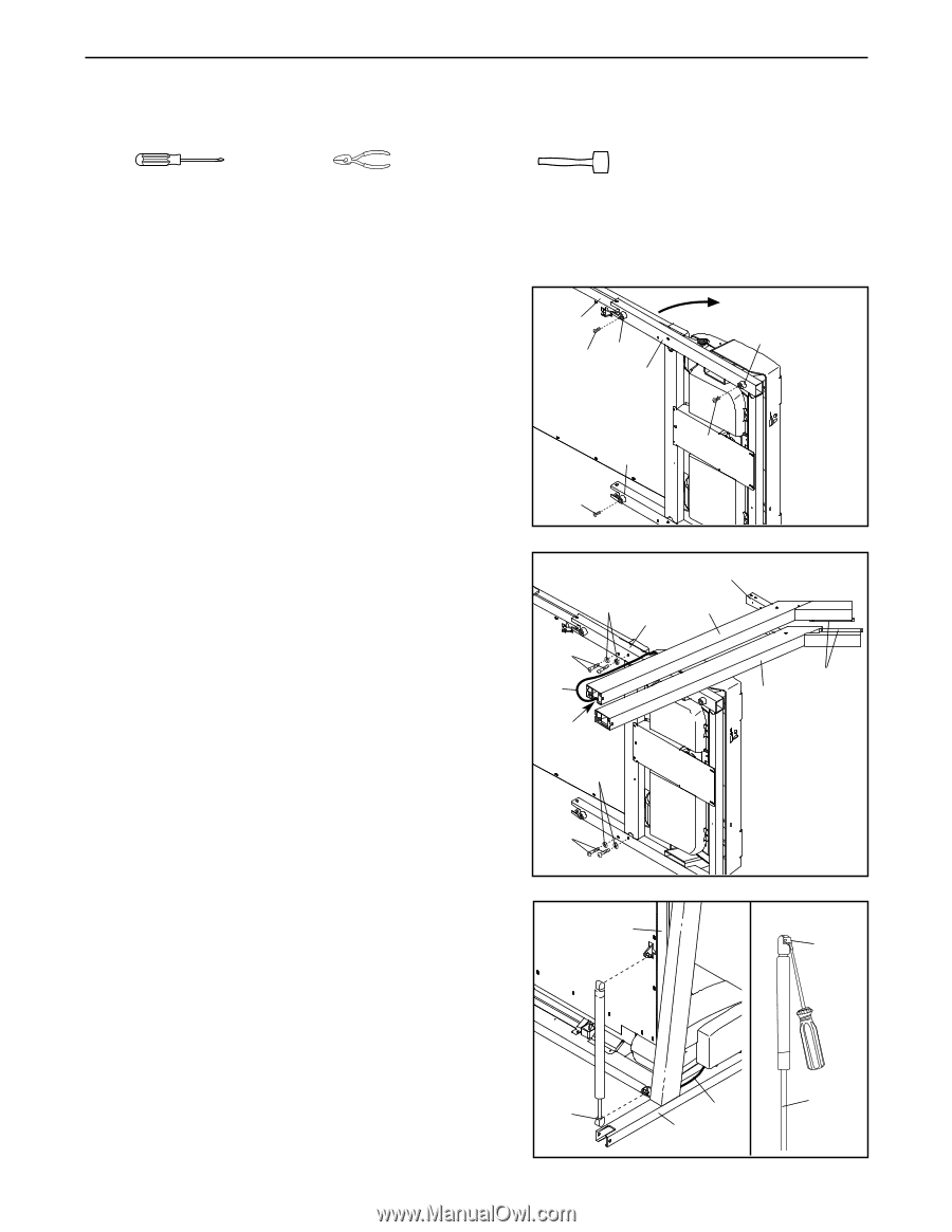
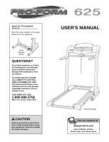
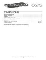
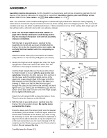
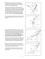
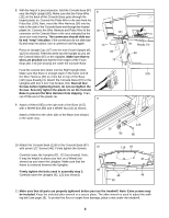
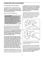
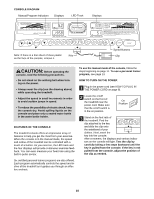
ASSEMBLY Assembly requires two persons. Set the treadmill in a cleared area and remove all packing materials. Do not dispose of the packing materials until assembly is completed. Assembly requires your own Phillips screw- driver , wire cutters and rubber mallet . Note: The underside of the treadmill walking belt is coated with high-performance lubricant. During shipping, a small amount of lubricant may be transferred to the top of the walking belt or the shipping carton. This is a normal condition and does not affect treadmill performance. If there is lubricant on top of the walking belt, simply wipe off the lubricant with a soft cloth and a mild, non-abrasive cleaner. 1. Note: Use the PART IDENTIFICATION CHART on page 23 to identify small parts used during assembly. Do not plug in the power cord until all assembly steps are completed. With the help of a second person, carefully tip the treadmill onto its left side as shown. Partially fold the Frame (12) so that the treadmill will be more stable. Do not fully fold the treadmill until it is completely assembled. Attach four Base Pads (97) to the bottom of the Base (115) with four 1" Tek Screws (108) (three are shown). 1 12 97 108 97 115 108 97 108 2. Identify the Right and Left Uprights (82, 122); the Right Upright has a half circle cutout in the lower end. The brackets on the Uprights should face each other. Hold the Right Upright (82) near the Base (115). Orient the Right Upright as shown, with the post on the indicated side. Straighten the Wire Harness (34), and feed it into the lower end of the Right Upright and out of the upper end. Leave enough slack in the lower end of the Wire Harness so that it lies flat on top of the Base (see drawing 3). Make sure that the Wire Harness goes through the cutout so that it will not be pinched, and hand tighten two 2 1/2" Bolts (124) with Washers (123) into the bottom of the Base and the lower end of the Right Upright. Do not tighten the Bolts yet. Attach the Left Upright (122) as described above. Note: There is not a wire harness on the left side. 3. With the help of a second person, carefully raise the Frame (12) to the position shown. Be careful not to overextend the Frame. Press the lower end of the Shock (105) onto the bracket on the Base (115) as shown. Press the upper end of the Shock onto the bracket on the Frame (12). Note: It may be necessary to move the Frame forward or backward to align the Shock with the bracket. It may be helpful to use a flat head screwdriver (see the inset drawing) to lift the metal clip on the Shock as you press the Shock onto the bracket. Do not remove the clip. Carefully lower the Frame (12). 6 2 123 115 124 34 Cutout Post 82 Brackets 122 123 124 3 12 Clip 105 105 34 115
-
 1
1 -
 2
2 -
 3
3 -
 4
4 -
 5
5 -
 6
6 -
 7
7 -
 8
8 -
 9
9 -
 10
10 -
 11
11 -
 12
12 -
13
-
14
-
15
-
16
-
17
-
18
-
19
-
20
-
21
-
22
-
23
-
24
-
25
-
26
 |
 |