ProForm 735 English Manual - Page 8
tighten the Nylon Locknuts yet. The Curl Post 42
 |
View all ProForm 735 manuals
Add to My Manuals
Save this manual to your list of manuals |
Page 8 highlights
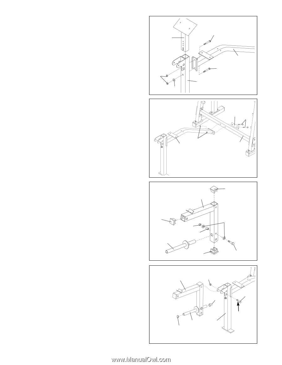
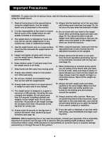
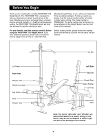
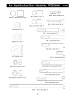
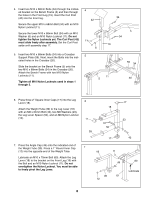
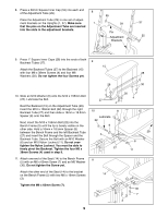
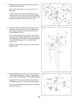
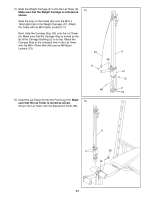
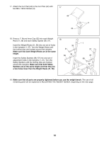
4. Insert two M10 x 68mm Bolts (34) through the indicated bracket on the Bench Frame (5) and then through the holes in the Front Leg (19). Insert the Curl Post (42) into the Front leg. Secure the upper M10 x 68mm Bolt (34) with an M10 Nylon Locknut (11). Secure the lower M10 x 68mm Bolt (34) with an M10 Washer (6) and an M10 Nylon Locknut (11). Do not tighten the Nylon Locknuts yet. The Curl Post (42) must slide freely after assembly. Set the Curl Post aside until assembly step 17. 4 42 11 6 34 5 34 19 5. Insert two M10 x 68mm Bolts (34) into a Crossbar 5 Support Plate (59). Next, insert the Bolts into the indi- cated holes in the Crossbar (20). Slide the bracket on the Bench Frame (5) onto the two M10 x 68mm Bolts (34) in the Crossbar (20). Attach the Bench Frame with two M10 Nylon Locknuts (11). Tighten all M10 Nylon Locknuts used in steps 1 through 5. 11 5 59 34 20 6. Press three 2Ó Square Inner Caps (17) into the Leg 6 Lever (18). Attach the Weight Tube (39) to the Leg Lever (18) with an M8 x 64mm Bolt (43), two M8 Washers (23), the Leg Lever Spacer (50), and an M8 Nylon Locknut (13). 17 39 18 13 50 17 17 23 43 7. Press the Angle Cap (49) onto the indicated end of the Weight Tube (39). Press a 1Ó Round Inner Cap 7 (12) into the opposite end of the Weight Tube. Lubricate an M10 x 75mm Bolt (60). Attach the Leg Lever (18) to the bracket on the Front Leg (19) with the Bolt and an M10 Nylon Locknut (11). Do not overtighten the Nylon Locknut. You must be able to freely pivot the Leg Lever. 18 11 49 39 19 12 60 Lubricate 8
-
 1
1 -
2
-
 3
3 -
 4
4 -
 5
5 -
 6
6 -
 7
7 -
 8
8 -
 9
9 -
 10
10 -
 11
11 -
 12
12 -
 13
13 -
14
-
15
-
16
-
17
-
18
-
19
-
20
-
21
-
22
 |
 |