ProForm 735 English Manual - Page 9
Backrest Tube. Secure the Bolt with an M10 Washer
 |
View all ProForm 735 manuals
Add to My Manuals
Save this manual to your list of manuals |
Page 9 highlights
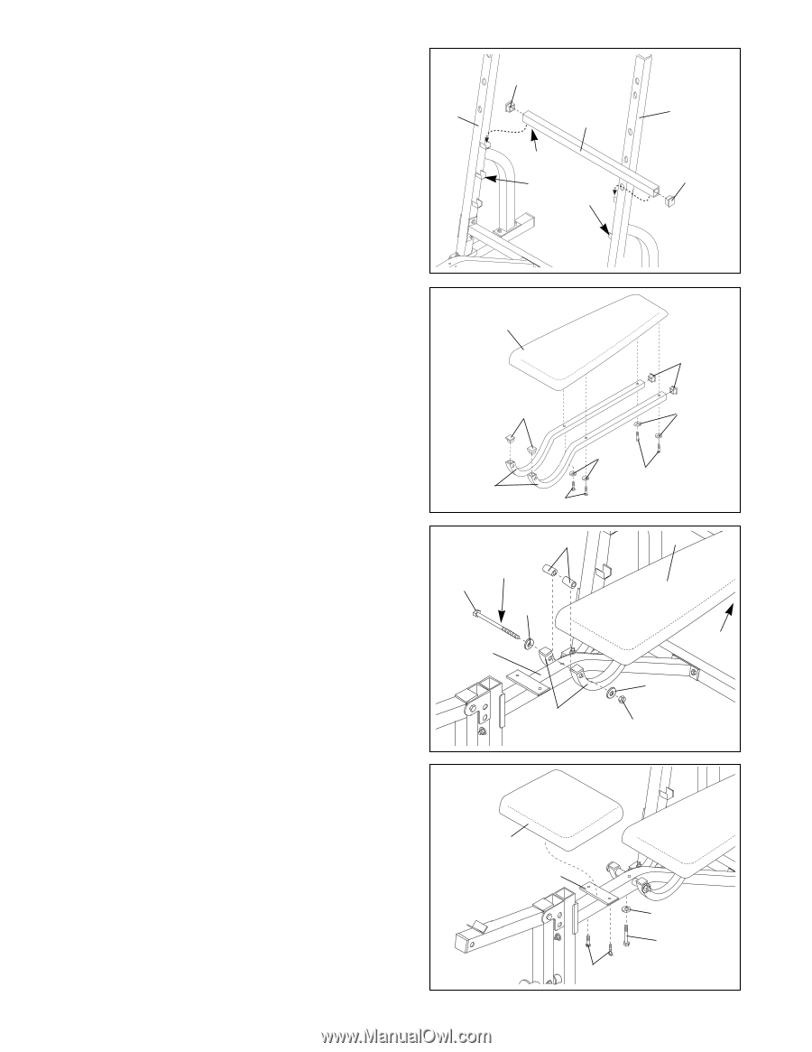
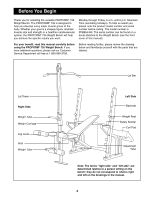
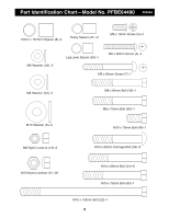
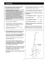
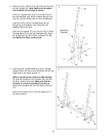
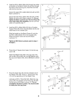
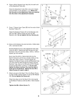
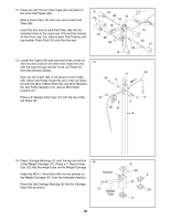
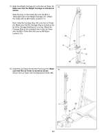
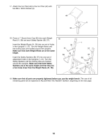
8. Press a 30mm Square Inner Cap (55) into each end of the Adjustment Tube (29). 8 Place the Adjustment Tube (29) in one set of adjust- ment brackets on the Uprights (1, 37). Make sure 1 that the pins on the Adjustment Tube are inserted into the slots in the adjustment brackets. 55 29 Pin Adjustment Brackets 37 55 9. Press 1Ó Square Inner Caps (28) into the ends of both Backrest Tubes (27). 9 15 Attach the Backrest Tubes (27) to the Backrest (15) with four M6 x 38mm Screws (4) and four M6 28 Washers (30). Do not tighten the four Screws yet. 28 30 10. Slide an M10 Washer (6) onto the M10 x 155mm Bolt (22). Lubricate the Bolt. 30 4 27 4 Rest the Backrest (15) on the Adjustment Tube (29). Insert the M10 x 155mm Bolt (22) through the right Backrest Tube (27) and then slide a 16mm x 18.5mm 10 8 15 Spacer (8) onto the Bolt. Lubricate 22 Next, insert the M10 x 155mm Bolt (22) into the Bench Frame (5) until the tip is barely visible on the 6 other side. Hold a 16mm x 18.5mm Spacer (8) between the Bench Frame and the left Backrest Tube 29 (27) and insert the Bolt through the Spacer and the 5 Backrest Tube. Secure the Bolt with an M10 Washer (6) and an M10 Nylon Locknut (11). Do not over- 6 tighten the Nylon Locknut. You must be able to freely pivot the Backrest. Tighten the four M6 x 38mm Screws (4) used in step 9. 27 11 11. Attach one end of the Seat (14) to the Bench Frame 11 (5) with an M6 x 63mm Screw (7) and an M6 Washer (30). Do not tighten the Screw yet. Attach the other end of the Seat (14) to the bracket on the Bench Frame (5) with two M6 x 16mm Screws (3). 14 5 Tighten the M6 x 63mm Screw (7). 30 7 3 9
-
 1
1 -
2
-
3
-
 4
4 -
 5
5 -
 6
6 -
 7
7 -
 8
8 -
 9
9 -
 10
10 -
 11
11 -
 12
12 -
 13
13 -
 14
14 -
15
-
16
-
17
-
18
-
19
-
20
-
21
-
22
 |
 |