ProForm 785 Watts Bike Uk Manual - Page 7
Post 6 with the Handlebar Clamp 22, the Clamp
 |
View all ProForm 785 Watts Bike manuals
Add to My Manuals
Save this manual to your list of manuals |
Page 7 highlights
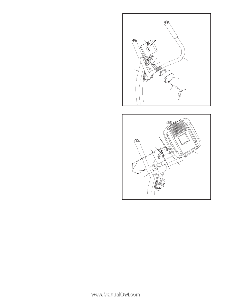
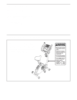
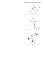
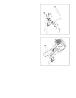
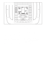
5. While a second person holds the Handlebar (7) near the Handlebar Post (6), insert the Left and Right Controller Wires (59, 60) into the hole in the Handlebar Post and upward out of the top of the Handlebar Post. Next, attach the Handlebar (7) to the Handlebar Post (6) with the Handlebar Clamp (22), the Clamp Cover (75), and the Adjustment Handle (10). Note: The Adjustment Handle works like a spanner. Turn the Adjustment Handle clockwise, pull it away from the Handlebar, turn it counterclockwise, push it toward the Handlebar, and then turn it clockwise again. Repeat until the Handlebar is tight. Be careful not to pinch the Controller Wires (59, 60). Then, tighten an M4 x 16mm Screw (54) into the Clamp Cover (75), the Handlebar Clamp (22), and the Handlebar Post (6). 5 51 6 Avoid pinching the controller wires during this step 59 60 7 22 75 10 54 6. While another person holds the Console (9) near 6 the Handlebar (7), connect the console wire har- ness to the Upper Wire Harness (51). Next, connect the Right Controller Wire (60), which has a tag attached, to the console controller wire that also has a tag. Then, connect the Left Controller Wire (59) to the other console controller wire. Insert the excess wire downward into the Handlebar Post (6). Console Controller Wires 60 59 6 Attach the Console (9) to the Handlebar (7) with four M4 x 16mm Screws (54). Be careful not to pinch the wires. 54 7 9 Console Wire 51 Harness Avoid pinching the wires during this step 7
-
 1
1 -
 2
2 -
 3
3 -
 4
4 -
 5
5 -
 6
6 -
 7
7 -
 8
8 -
 9
9 -
 10
10 -
 11
11 -
 12
12 -
13
-
14
-
15
-
16
-
17
-
18
-
19
-
20
-
21
-
22
-
23
-
24
 |
 |