ProForm Xp210 U Bike English Manual
ProForm Xp210 U Bike Manual
 |
View all ProForm Xp210 U Bike manuals
Add to My Manuals
Save this manual to your list of manuals |
ProForm Xp210 U Bike manual content summary:
- ProForm Xp210 U Bike | English Manual - Page 1
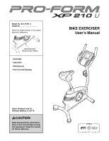
above for reference. Serial Number Decal (under frame) •• Assembly •• Operation •• Maintenance •• Part List and Drawing BIKE EXERCISER User’'s Manual Sears, Roebuck and Co. Hoffman Estates, IL 60179 CAUTION Read all precautions and instructions in this manual before using this equipment. Keep this - ProForm Xp210 U Bike | English Manual - Page 2
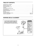
DECAL PLACEMENT 2 IMPORTANT PRECAUTIONS 3 BEFORE YOU BEGIN 4 PART IDENTIFICATION CHART 5 ASSEMBLY 6 HOW TO USE THE EXERCISE BIKE 12 FCC INFORMATION 18 MAINTENANCE AND TROUBLESHOOTING 19 EXERCISE GUIDELINES 21 PART LIST 22 EXPLODED DRAWING 23 ORDERING REPLACEMENT PARTS Back Cover 90 DAY - ProForm Xp210 U Bike | English Manual - Page 3
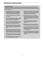
IMPORTANT PRECAUTIONS WARNING: To reduce the risk of serious injury, read all important precautions and instructions in this manual and all warnings on your exercise bike before using your exercise bike. Sears assumes no responsibility for personal injury or property damage sustained by or through - ProForm Xp210 U Bike | English Manual - Page 4
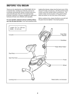
BEFORE YOU BEGIN Thank you for selecting the new PROFORM® XP 210 U exercise bike. Cycling is an effective exercise for increasing cardiovascular fitness, building endurance, and toning the body. The XP 210 U exercise bike provides a selection of features designed to make your workouts at home more - ProForm Xp210 U Bike | English Manual - Page 5
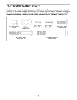
for assembly. The number in parentheses below each drawing is the key number of the part, from the PART LIST near the end of this manual. The number following the key number is the quantity needed for assembly. Note: If a part is not in the hardware kit, check to see if - ProForm Xp210 U Bike | English Manual - Page 6
ASSEMBLY •• Assembly requires two persons. •• Place all parts in a cleared area and remove the packing materials. Do not dispose of the packing materials until you nish all assembly steps. •• Left parts are marked “"L”" or “"Left”" and right parts are marked “"R”" or “"Right.”" •• To identify - ProForm Xp210 U Bike | English Manual - Page 7
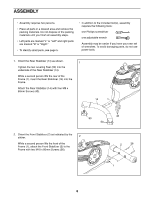
3. Orient the Upright (3) as shown. Have a second person hold the Upright near the Frame (1). 3 Locate the wire tie in the lower end of the Upright (3). Tie the wire tie to the Main Wire (31). Then, pull the upper end of the wire tie until the Main Wire is routed through the Upright. Tip: To - ProForm Xp210 U Bike | English Manual - Page 8
5. Orient the Top Shield (9) as shown. Slide the Top Shield onto the Upright (3). 5 Attach the Top Shield (9) to the Frame (1) with two M4 x 16mm Screws (40). Orient the Top Shield Cap (10) as shown. Press the Top Shield Cap onto the Left and Right Shields (17, 18). 10 17, 18 40 3 9 1 6. - ProForm Xp210 U Bike | English Manual - Page 9
7. Loosen and remove the Seat Knob (11) from the Seat Carriage (30). 7 Look underneath the Seat (12), and locate the Carriage Block (55) inside the Seat Carriage (30). Orient the Seat Post (5) as shown. Set the Seat Carriage (30) in the bracket on the Seat Post. Next, insert the Seat Knob (11) - ProForm Xp210 U Bike | English Manual - Page 10
the battery compartments. Then, reattach the battery covers. To purchase an optional power adapter, call the telephone number on the cover of this manual. To avoid damaging the console, use only a manufacturer-supplied power adapter. Plug one end of the power adapter into the receptacle inside the - ProForm Xp210 U Bike | English Manual - Page 11
strap on the Left Pedal (not shown) in the same way. 49 3 54 Strap 13 26 Tab 15. Make sure that all parts of the exercise bike are properly tightened. Note: Extra parts may be included. To protect the floor or carpet from damage, place a mat under the - ProForm Xp210 U Bike | English Manual - Page 12
HOW TO USE THE EXERCISE BIKE HOW TO LEVEL THE EXERCISE BIKE If the exercise bike rocks slightly on your floor during use and then firmly tighten the seat knob. Knob HOW TO ADJUST THE SEAT POST For effective exercise, the seat should be at the proper height. As you pedal, there should be a - ProForm Xp210 U Bike | English Manual - Page 13
manual mode of the console, you can change the resistance of the pedals with the touch of a button. As you exercise, the console will provide continuous exercise the pedals and prompts you to vary your pedaling speed as it guides you through an effective workout. The console also features the iFit - ProForm Xp210 U Bike | English Manual - Page 14
is selected, this display mode will show the time remaining in the workout. Track—-When the manual mode is selected, this display mode will show a track representing 1/4 mile (400 m). As you exercise, indicators will appear in succession around the track until the entire track appears. The track - ProForm Xp210 U Bike | English Manual - Page 15
optimal performance, clean the contacts using a soft cloth; never use alcohol, abrasives, or chemicals to clean the contacts. 6. When you are finished exercising, the console will turn off automatically. If the pedals do not move for several seconds, a series of tones will sound, the console will - ProForm Xp210 U Bike | English Manual - Page 16
the lower display. 3. Begin pedaling to start the workout. As you exercise, keep your pedaling speed near the goal speed for the current segment. for the current segment is too high or too low, you can manually override the setting by pressing the Resistance buttons. IMPORTANT: When the current - ProForm Xp210 U Bike | English Manual - Page 17
after you select a workout, the voice of a personal trainer will begin guiding you through your workout. iFit workouts function in the same way as preset see steps 3 to 6 starting on page 16. 3. When you are finished exercising, remove the iFit card. 2. Insert an iFit card and select a workout. - ProForm Xp210 U Bike | English Manual - Page 18
been used since the exercise bike was purchased. The lower display will show the total distance that the pedals have moved since the exercise bike was purchased. 4. Exit , if not installed and used in accordance with the instructions, may cause harmful interference to radio communications. However, - ProForm Xp210 U Bike | English Manual - Page 19
the console out of direct sunlight. CONSOLE TROUBLESHOOTING If the console display becomes dim, replace all the batteries at the same time; most console problems are the result of low batteries. See assembly step 11 on page 10 for replacement instructions. If the console does not display your - ProForm Xp210 U Bike | English Manual - Page 20
need to be adjusted. To adjust the drive belt, you must remove the top shield cap, the top shield, and the right shield (see the instructions below). Using a flat screwdriver, remove the Top Shield Cap (10). Then, remove the two M4 x 16mm Screws (40) and lift the Top Shield (9) away from - ProForm Xp210 U Bike | English Manual - Page 21
heart rate as a guide to find the proper intensity level. The chart below shows recommended heart rates for fat burning and aerobic exercise. To find the flexibility of your muscles and helps to prevent post-exercise problems. EXERCISE FREQUENCY To maintain or improve your condition, complete three - ProForm Xp210 U Bike | English Manual - Page 22
Handlebar Cap 52 1 Pulse Wire 53 2 M8 x 16mm Screw 54 2 M4 x 22mm Screw 55 1 Carriage Block 56 4 M8 Washer * –- User’'s Manual * –- Assembly Tool Note: Specifications are subject to change without notice. For information about ordering replacement parts, see the back cover of - ProForm Xp210 U Bike | English Manual - Page 23
EXPLODED DRAWING Model No. 831.21941.3 R0712A 40 40 6 40 40 40 40 17 40 55 12 18 40 46 51 51 40 52 19 40 30 56 45 37 24 34 5 11 56 45 35 10 37 20 47 31 8 40 44 9 28 48 41 1 29 27 32 42 38 21 40 22 7 46 3 54 49 44 44 15 45 45 36 16 2 15 38 4 35 14 50 43 43 39 53 - ProForm Xp210 U Bike | English Manual - Page 24
for free repair (or replacement if repair proves impossible). There is a 5 year warranty on the frame. This warranty does not apply when the Bike Exerciser is used commercially or for rental purposes. This warranty gives you specific legal rights, and you may also have other rights which vary from
-
 1
1 -
 2
2 -
 3
3 -
 4
4 -
 5
5 -
 6
6 -
 7
7 -
8
-
9
-
10
-
11
-
12
-
13
-
14
-
15
-
16
-
17
-
18
-
19
-
20
-
21
-
22
-
23
-
24
 |
 |
Serial Number
Decal (under frame)
CAUTION
Read all precautions and instruc-
tions in this manual before using
this equipment. Keep this manual
for future reference.
Model No. 831.21941.3
Serial No.
Write the serial number in the space
above for reference.
BIKE EXERCISER
User°s Manual
± Assembly
± Operation
± Maintenance
± Part List and Drawing
Sears, Roebuck and Co.
Hoffman Estates, IL 60179