ProForm Xp210 U Bike English Manual - Page 6
Assembly
 |
View all ProForm Xp210 U Bike manuals
Add to My Manuals
Save this manual to your list of manuals |
Page 6 highlights
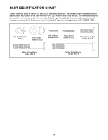
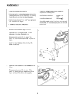
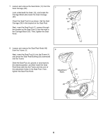
ASSEMBLY •• Assembly requires two persons. •• Place all parts in a cleared area and remove the packing materials. Do not dispose of the packing materials until you nish all assembly steps. •• Left parts are marked “"L”" or “"Left”" and right parts are marked “"R”" or “"Right.”" •• To identify small parts, see page 5. •• In addition to the included tool(s), assembly requires the following tools: one Phillips screwdriver one adjustable wrench Assembly may be easier if you have your own set of wrenches. To avoid damaging parts, do not use power tools. 1. Orient the Rear Stabilizer (14) as shown. 1 Tighten the two Leveling Feet (50) into the underside of the Rear Stabilizer (14). While a second person lifts the rear of the Frame (1), insert the Rear Stabilizer (14) into the Frame. Attach the Rear Stabilizer (14) with four M8 x 60mm Screws (43). 14 1 50 50 2. Orient the Front Stabilizer (2) as indicated by the sticker. 2 While a second person lifts the front of the Frame (1), attach the Front Stabilizer (2) to the Frame with two M10 x 80mm Screws (36). 43 2 36 1 6
-
 1
1 -
 2
2 -
 3
3 -
 4
4 -
 5
5 -
 6
6 -
 7
7 -
 8
8 -
 9
9 -
 10
10 -
 11
11 -
 12
12 -
13
-
14
-
15
-
16
-
17
-
18
-
19
-
20
-
21
-
22
-
23
-
24
 |
 |
