Samsung RB215BSSB Service Manual - Page 47
Source Power Circuit, 2 Oscillation Circuit
 |
View all Samsung RB215BSSB manuals
Add to My Manuals
Save this manual to your list of manuals |
Page 47 highlights
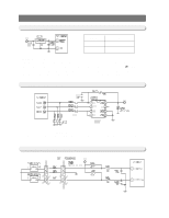
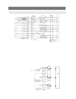
OPERATION PRINCIPLES BY PARTS OF CIRCUIT 12-1) SOURCE POWER CIRCUIT Power Vcc(DC 5V) +12V(DC 12V) Circuit MICOM POWER AND SENSORS RELAY,PANEL DRIVING CIRCUIT 1) When the power is supplied,AC voltage stepped down on the 2nd transformer flows between ①and ③at about AC 16V and changes to DC voltage when it goes through the diode D101 and D108,and constant 12V will be output via regulator REG1(7812).And,it will supply DC5V to MICOM and power to other circuits via regulator REG2 (MC7805ACT),and make entire PCB operate. 12-2) OSCILLATION CIRCUIT Terminal Xin(#19) Xout(#18) Oscillation Freq. 8MHz 8MHz 1) It is an Oscillation Circuit for synchronism clock generation and time calculation on the information sending &receiving of the MICOM internal logic elements and when specifications for Resonator change,the timing system of MICOM changes resulting in errors. (Rated parts must be used) 47
-
 1
1 -
2
-
3
-
4
-
5
-
6
-
7
-
8
-
9
-
10
-
11
-
12
-
13
-
14
-
15
-
16
-
17
-
18
-
19
-
20
-
21
-
22
-
23
-
24
-
25
-
26
-
27
-
28
-
29
-
30
-
31
-
32
-
33
-
34
-
35
-
36
-
37
-
38
-
39
-
40
-
41
-
 42
42 -
 43
43 -
 44
44 -
 45
45 -
 46
46 -
 47
47 -
 48
48 -
 49
49 -
 50
50 -
 51
51 -
 52
52 -
53
-
54
-
55
-
56
-
57
-
58
-
59
-
60
-
61
-
62
-
63
-
64
-
65
-
66
-
67
-
68
-
69
-
70
-
71
-
72
-
73
-
74
-
75
-
76
-
77
-
78
-
79
-
80
 |
 |
