Samsung RB215BSSB Service Manual - Page 60
When F-Room FANF-FANdoes not operate
 |
View all Samsung RB215BSSB manuals
Add to My Manuals
Save this manual to your list of manuals |
Page 60 highlights
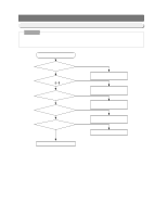
Diagnostics 13-4) When FAN does not operate Note "Check out the F-FAN with the Forced Operation selected" 1. F-Room FAN, R-Room FAN and COMP COOLING FAN remains OFF while COMP is off. (R-FAN can be on with the defrost function.) 2. When Comp is ON,R-FAN does not always remain ON (including Forced Operaation) and when R-Room temp reaches to set temp,R-FAN remains OFF. 3. When R-Room &F-Room are closed after being opened,each FAN starts up with a delay time (5sec ~1min) immediately.(Comp ON condition) 1) When F-Room FAN(F-FAN)does not operate Start Is it during Forced Operation? NO YES Does Fan operate with DOOR S/W presses? (Including Delay Time) NO Is DOOR S/W normal? YES Is the voltage of MICOM #42 5V (Close condition)? YES Freezer Door Switch input #42 Is insertion of CN71⑪PIN(YELLOW)of MAIN PCB normal? YES Is voltage of MICOM Pin #27 "HIGH"(5V)? YES Is voltage of IC70 #14 "LOW"(0.7V)? YES Is F-FAN RELAY(SSR71) normal? YES Start Forced Operation Normal R-FAN NO Change DOOR S/W NO Check soldering /Change PCB NO Re-insert ConnectorCN71 NO Check soldering /Change PCB NO Check IC70 /Change PCB NO Check wire assembled status/Change MAIN PCB ASS'Y 60 Check RELAY /Change PCB - Reference • Load terminal Measure method.
-
 1
1 -
2
-
3
-
4
-
5
-
6
-
7
-
8
-
9
-
10
-
11
-
12
-
13
-
14
-
15
-
16
-
17
-
18
-
19
-
20
-
21
-
22
-
23
-
24
-
25
-
26
-
27
-
28
-
29
-
30
-
31
-
32
-
33
-
34
-
35
-
36
-
37
-
38
-
39
-
40
-
41
-
42
-
43
-
44
-
45
-
46
-
47
-
48
-
49
-
50
-
51
-
52
-
53
-
54
-
 55
55 -
 56
56 -
 57
57 -
 58
58 -
 59
59 -
 60
60 -
 61
61 -
 62
62 -
 63
63 -
 64
64 -
 65
65 -
66
-
67
-
68
-
69
-
70
-
71
-
72
-
73
-
74
-
75
-
76
-
77
-
78
-
79
-
80
 |
 |
