Samsung RS257BABB Service Guide - Page 39
Door S/W Sensing Circuit, 5 Temperature Sensing Circuit
 |
View all Samsung RS257BABB manuals
Add to My Manuals
Save this manual to your list of manuals |
Page 39 highlights
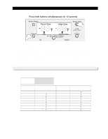
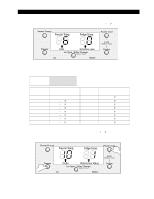
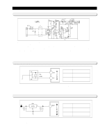
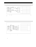
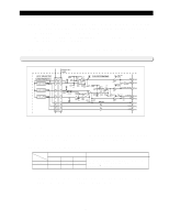
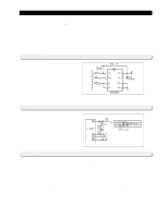
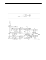
Circuit Descriptions 10-4) Door S/W Sensing Circuit Terminal Operation Volt(state) DOOR CLOSE 0V (LOW) Freezer DOOR OPEN 5V (HIGH) DOOR CLOSE 0V (LOW) Ref. DOOR OPEN 5V (HIGH) 1) The terminals, ② and ⑥ of the connector (CN30) are grounded, and DC5V (Vcc) is supplied to the terminals, ⑤ and ⑥ through the resistors, R404 and R403 for the freezer and the refrigerator door, respectively. 2) The micro-processor senses the door's open and close based on engaged voltages, "Low(0V)" and "High(5V)," respectively. Note) The door switch always should be checked when the evaporator fan is not running while the door is closed. 10-5) Temperature Sensing Circuit # of terminal in MICOM PIN #49 (F-SENSOR) PIN #50 (F-DEF-SENSOR) PIN #52 (R-SENSOR) PIN #53 (R-DEF-SENSOR) Remark Micom terminal voltage may change according to temp. 1) A thermistor with a negative temperature coefficient (NTC) is used for a temperature sensor. 2) Resistors, R 301 � R304 and capacitors, C 301 � C 305 are used for a noise protection purpose. 3) For the F-sensor, the input voltage into the micro processor (MICOM), VF is calculated by (Rth x Vcc)/(R301+ Rth), where Rth is a corresponding resistance to the thermistor's output (See Ref. 6 in Appendix). 4) The F-Def sensor is connected with a bimetal and a temperature sensor is in parallel. In a normal operation of the system, the bimetal is on and 0V is input into the micro-processor. During a defrost cycle, the bimetal will be off from 54℉, and a divided voltage with R304 enter to the micro-processor to keep sensing the set temperature. 39
-
 1
1 -
2
-
3
-
4
-
5
-
6
-
7
-
8
-
9
-
10
-
11
-
12
-
13
-
14
-
15
-
16
-
17
-
18
-
19
-
20
-
21
-
22
-
23
-
24
-
25
-
26
-
27
-
28
-
29
-
30
-
31
-
32
-
33
-
 34
34 -
 35
35 -
 36
36 -
 37
37 -
 38
38 -
 39
39 -
 40
40 -
 41
41 -
 42
42 -
 43
43 -
 44
44 -
45
-
46
-
47
-
48
-
49
-
50
-
51
-
52
-
53
-
54
-
55
-
56
-
57
-
58
-
59
-
60
-
61
-
62
-
63
-
64
-
65
-
66
 |
 |
