Samsung RS257BABB Service Guide - Page 56
Reference for circuit diagnostics
 |
View all Samsung RS257BABB manuals
Add to My Manuals
Save this manual to your list of manuals |
Page 56 highlights
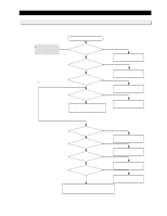
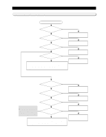
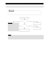
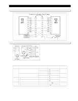
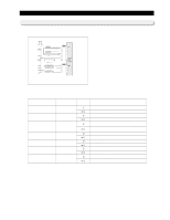
12. Reference for circuit diagnostics 12-1) Wire connector on the cabinet door. 12- 2) How to check relay failure Note) NC -> Normally Close (C terminal and ON terminal) NO -> Normally Open (C terminal and Open terminal) C -> Common Terminal Disconnect the connector of the main PCB CN70 and CN71, then check the follows : 1. Measure the voltage at both terminals of a coil and determine if the relay is working. 2. Measure the voltage at both terminals of a trigger and determine if SSR is working. 3. Measure the resistance at both terminals of a load contact, and determine if there is an error in voltages of coil and trigger. Div. of contact Voltage at both terminal of coil and trigger Both terminals of contact Resistance value 3-contact terminal Relay DC 12V (Working Condition) DC 0V (Stop Condition) 2-contact terminal Relay SSR � DC 12V (load working condition) �DC 0V (load stop condition) �DC 12V (load working condition) �DC 0V (load stop condition) Between C and NO 0Ϊ (Short) -> Normal Between C and NC ∞Ϊ (Open) -> Normal Between C and NO ∞Ϊ (Open) -> Normal Between C and NC 0Ϊ (Short) -> Normal Between both terminals of contact 0Ϊ (Short) -> Normal Between both terminals of contact ∞Ϊ (Open) -> Normal Between both terminals of contact About 4-5㏀ (Short) -> Normal Between both terminals of contact ∞Ϊ (Open) -> Normal 56
-
 1
1 -
2
-
3
-
4
-
5
-
6
-
7
-
8
-
9
-
10
-
11
-
12
-
13
-
14
-
15
-
16
-
17
-
18
-
19
-
20
-
21
-
22
-
23
-
24
-
25
-
26
-
27
-
28
-
29
-
30
-
31
-
32
-
33
-
34
-
35
-
36
-
37
-
38
-
39
-
40
-
41
-
42
-
43
-
44
-
45
-
46
-
47
-
48
-
49
-
50
-
 51
51 -
 52
52 -
 53
53 -
 54
54 -
 55
55 -
 56
56 -
 57
57 -
 58
58 -
 59
59 -
 60
60 -
 61
61 -
62
-
63
-
64
-
65
-
66
 |
 |
