Samsung RS257BABB Service Guide - Page 58
Check Door S/W
 |
View all Samsung RS257BABB manuals
Add to My Manuals
Save this manual to your list of manuals |
Page 58 highlights
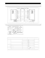
Reference for circuit diagnostics 12-4) Check sensors Disconnect the connector from the Main PCB, than measure the resistance of the following sensors. 1. Check the resistance the Freezer sensor between the CN30 ③ and CN72 ⑦ 2.Check the resistance the Fridge Room sensor between the CN30 ⑦ and CN72 ⑦ 3. Check the resistance the F Defrosting sensor between the CN30 ④ and CN72 ⑦ 4. Check the resistance the R Defrosting sensor between the CN30 ⑧ and CN72 ⑦ 5. Check the resistance between the no.③ and ④ of the Ice-Maker sensor cn90. 6. Check the resistance between the no.⑬ and ⑭ of the CoolSelect ZoneTM sensor cn51. 7. Decide the sensor by comparing above resistances to the temperature of each sensor with the conversion table of sensor resistance and voltage from the reference temperature of Ref. 6 on this manual. ※When the resistance is ∞Ϊor 0Ϊ,check the connection of electric wire and sensorconnector. 12-5) Check Door S/W Check the condition in power on. Door S/W have 2 contact points. One contact point perceives the door open/close by DC 5V on the PCB. Another contact point turns on/off the Lamp. (Lamp on the REF) 1. If the Lamp turns on correctly when the door is open, it is normal. Press the door s/w and check it the lamp turns off. If it doesn't work properly, check the door s/w on the refrigerator. (Door open on the REF and the sensor part of the Main PCB) 1. Check the voltage between no. 5 "+" terminal and no.6 "-" terminal of CN30. 2. If 5V is checked when the door is open, it is normal. 3. If 0V is checked when the door is closed, it is normal. If it is not, check the door s/w and electric wire connection. (Lamp on the FRE) 1. If the Lamp turns on correctly when the door is open, it is normal. Press the door s/w and check it the lamp turns off. If it doesn't work properly, check the door s/w on the FRE. (Door open on the FRE and the sensor part of the Main PCB) 1. Check the voltage between no. 1 "+" terminal and no.2 "-" terminal of CN30. 2. If 5V is checked when the door is open, it is normal. 3. If 0V is checked when the door is closed, it is normal. If it is not, check the door s/w and electric wire connection. 58
-
 1
1 -
2
-
3
-
4
-
5
-
6
-
7
-
8
-
9
-
10
-
11
-
12
-
13
-
14
-
15
-
16
-
17
-
18
-
19
-
20
-
21
-
22
-
23
-
24
-
25
-
26
-
27
-
28
-
29
-
30
-
31
-
32
-
33
-
34
-
35
-
36
-
37
-
38
-
39
-
40
-
41
-
42
-
43
-
44
-
45
-
46
-
47
-
48
-
49
-
50
-
51
-
52
-
 53
53 -
 54
54 -
 55
55 -
 56
56 -
 57
57 -
 58
58 -
 59
59 -
 60
60 -
 61
61 -
 62
62 -
 63
63 -
64
-
65
-
66
 |
 |
