Seiko 6A32 Technical Guide - Page 12
direction of mounting.
 |
View all Seiko 6A32 manuals
Add to My Manuals
Save this manual to your list of manuals |
Page 12 highlights
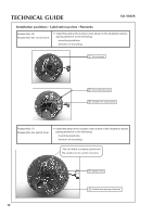
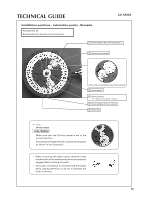
TECHNICAL GUIDE Cal. 6A32A Installation positions • Lubrication points • Remarks Reassembly (6) Reassemble the circuit block. ❇ Install the parts in the number order shown in the illustration below, paying attention to the following: mounting positions, direction of mounting. 1 Circuit block 2 Circuit block screw 3 Insulator for circuit block Reassembly (7) Reassemble the switch lever. ❇ Install the parts in the number order shown in the illustration below, paying attention to the following: mounting positions, direction of mounting. The coil block is closely positioned. Be careful not to cut the coil wire. 1 Switch lever 2 Switch lever springs (4 pieces) 12
-
 1
1 -
2
-
3
-
4
-
5
-
6
-
 7
7 -
 8
8 -
 9
9 -
 10
10 -
 11
11 -
 12
12 -
 13
13 -
 14
14 -
 15
15 -
 16
16 -
 17
17 -
18
-
19
-
20
-
21
-
22
-
23
-
24
 |
 |

12
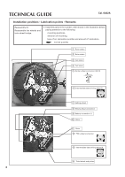
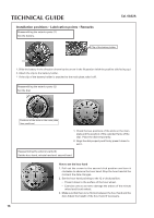
TECHNICAL GUIDE
Cal. 6A32A
Reassembly (6)
Reassemble the circuit block.
❇
Install the parts in the number order shown in the illustration below,
paying attention to the following:
mounting positions,
direction of mounting.
Installation positions • Lubrication points • Remarks
1
Circuit block
2
Circuit block screw
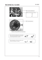
2
Switch lever springs (4 pieces)
1
Switch lever
3
Insulator for circuit block
Reassembly (7)
Reassemble the switch lever.
❇
Install the parts in the number order shown in the illustration below,
paying attention to the following:
mounting positions,
direction of mounting.
The coil block is closely positioned.
Be careful not to cut the coil wire.