Sennheiser EM 1036 Instructions for Use - Page 10
light., Antennas, antenna, connection, Operating, permit, Examples
 |
View all Sennheiser EM 1036 manuals
Add to My Manuals
Save this manual to your list of manuals |
Page 10 highlights
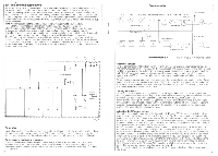
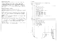
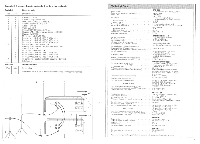
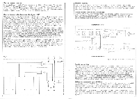
Indicator field strength/awing The LED display (7) shows in logarithmic scale the RF-input or the modulation in percentage. Selection is with button (4). Indication of frequency variation (only EME1038,EME1036 R andEME1036-90) Three LEDs (1) above the LED display (7) indicate if the incoming frequency is within the tolerance fringe. If the frequency lies within this range, the green LED will be lit Frequency variations cause the left (-) or the right (+) LED to light. In such a case you should check the transmitter. Strong frequency variations will cause not only a reduction of transmission quality but also a decrease in effective radius. Antennas and antenna connection The following antennas are available for the three versions of EM 1036: GZA 1000: Half-wave dipol; frequency range: 35-45 MHz; length: approx. 3.8 m; length of antenna cable: 5 m, RG 58; impedance; 50O; connection: BNC-plug. Tripod and pole fixture damps are also supplied. GZA 1001: Telescope antenna, due to adjustable length suitable for the 35-240 MHz frequency range. max. length: 1.5 m, min. length: 30 a-n, attachment and connection only with the tripod adapter GZS 1001. as the tripod is included in the functioning of the antenna. Impedance: 50O; connection: BIC-socket. GZA 1002: Half-wave dipol; frequency range: 170-220 MHz; length: approx 90 cm; connection and attachment with the supporting device GZH 1002; length of antenna cable; approx 5 m, RG 58; connection: without connection plug. GZA 1036-9: Ground-plane antenna for the frequency range 130-250 MHz. Frequency adjustment by shortening the antenna rods. RF-socket type N (male). %" thread for floor stand mounting. For connection of the antennas the coaxial aide type RG 58 can be used for the range 30-45 MHz. For systems working in the 2-m-band (138-250 MHz), the RG 213 should be used. This cable is thicker and not as flexible as the RG 58, but has less cable loss for this frequency range. Operating permit The use of wireless microphone systems is generally subject to local licenang or permit arrangements. For further details contact your local Sennheiser distributor. Examples Example 1: 5-channel non-diversity system for 2 m band (narrowband) Pane list Receiver side Pos. Units Designation 1 Antenna GZA 1002 lot 179 tell lz 2 Antenna support GZH 1002 3 BNC-plug for 5 mm cable diameters 4 BNC-double plug GZV 1019 A 5 Antenna cable GZL 1019 A 10 6 Adapter BNC-N 7 Receiver EM 1036 consisting of: Housing EMG 1036 or carrying case EMK 1036 Chassis EMC 1036 Monitor module EMM 1036 Receiver module EME 1036-9, 179.00 MHz Receiver module EME 1036-9, 179.08 MHz Receiver module EME 1036-9, 179.24 MHz Receiver module EME 1036-9, 179.36 MHz Receiver module EME 1036-9. 179.56 MHz 8 5 9 2 Cover plate EMB 1026 AF-connecting cable with XLR-3 coupling (Cannon). e. g. KA 7 U Adapter cable GZL 1036 Parts list Pos. Units 1 1 1 1 1 2 2 2 2 Transmitter tilde Designation Transmitter SK 1012-9, 179.00 MHz Transmitter SK 1012-9, 179.08 MHz Transmitter SK 2012-9, 179.24 MHz Transmitter SK 2012-9, 179.36 MHz Transmitter SKM 4031-9, 179.56 MHz Microphone MKE 10 Microphone MKE 10.2 R Microphone MKE 4012 Windscreen MZW 1010 AF AF 15 16
-
 1
1 -
2
-
3
-
4
-
 5
5 -
 6
6 -
 7
7 -
 8
8 -
 9
9 -
 10
10 -
 11
11 -
 12
12 -
 13
13 -
 14
14 -
 15
15 -
16
 |
 |
