Sennheiser EM 1036 Instructions for Use - Page 9
Operation
 |
View all Sennheiser EM 1036 manuals
Add to My Manuals
Save this manual to your list of manuals |
Page 9 highlights
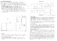
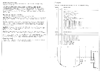
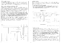
RE. and antenna connections As shown in Fig. 7 the signal delivered by the antenna is distributed from the antenna input 1 to receiver modules 1, 3 and 5 and from antenna input 2 to modules 2. 4 and 6. In this way, a 3-channel diversity system can, for instance, be fed by two antennas without additional equipment. Fig. 7 also shows that, if necessary, a DC-voltage can be switched onto the antenna inputs to teed antenna amplifiers through the antenna lead. The corresponding switches (21) are accessible after the removal of the monitor module EMM 1036. The position selected is indicated by two LEDs (13) on the front side. Hint: When measuring at the antenna inputs the DC-voltage must be switched off. Otherwise the measuring equipment might be damaged when connected. Should you consider inserting an antenna amplifier it should be taken into account that many amplifiers for multi-channel systems on the market often present more disadvantages than advantages. which is shown by a considerate deterioration in the intermodulation ratio. If an ampli- I fier has to be used because of long cables, only high quality sets should be employed. The RF-input resp. output sockets of an additional built-in diplexer are located underneath the antenna inputs. The sockets are marked with Aux 1, Aux 2 and Aux 3 (19). This additional diplexer is necessary e.g. for setting up a 6-channel system (Without diversity) if the set is lo be fed from one antenna only (see "Examples"). The diplexer is also required when connecting a 6-channel diversity system (see "Examples). Receiver module I Tuw C> Mixer IF-Ampliher Demodulate! HeymExpander AF -amplifier 20 dBattenuate! monitor output to Control voltage it Onnsisdy switch AF4evel adjustment AF-outpul MM Diversity match Mender output s C> I r :-.- AF-oulpui AF-level adjustment Ani, Ant Aux 2 I 1 23 r Antenna divider 1 2 3 4 5 6 Lv noiexer Fig. 7 Operation Once all AF and RF connections have been made. you should check if the modules, to which diversity operation is intended, are switched to "DIV" operation. For reasons of reliable transmission This set has been conceived for diversity operation, therefore it should generally be used in this way. Switching over to diversity operation Diversity transfer operation is only possible with adjacent receiver modules (1 and 2.3 and 4, 5 and 6). Another requirement is that both receiver modules be Set to the same frequency. For diversity operation the switches (2) of the modules which are to be coupled to diversity pairs must be in position I. 13 Receiver moduleII Rg 8: Principle of diversity operation "HiDyn" operation Like all companding systems the "HiDyn" system works with a level-dependent preemphasis on the transmitter side which is reversed on the receiver side. The receiver modules have been pre-set to 1-liDyn" operation at the factory. Only in special cases, if the receiver is not to be used together with "HiDyn" equipped transmitters the companding system may be switched off. The corresponding switch (22) is accessible after the receiver module has been pulled out of the chassis (Fig. 4). When these preparatory measures have been taken the receiver is switched on by pushing "Power' button (11). After the set has been turned on LED (12) lights up. Each receiver module can be put into operation separately by the push-button (3). The lower diode of the LED display (7), indicates the state of operation of the module in use. Setting the squelch To prevent disturbing noise it no signal at all or an RF-signal, which is too weak for a good transmission, reaches the receiver. the output of the receiver is switched oft by an electronic squelch. The threshold can be set for a value between 0 and 100p with the "Squelch" control (5). When switched through, the green LED (6) lights up. If there are difficulties with a disturbing transmitter, the threshold should be raised (with your transmitter switched off) until the interfering signal is reliably suppressed. With diversity operation the squelch of the two receiver modules of each diversity pair should be set to the same value. Adjusting the AF-output voltage The output level has been pre-set at the factory to + 6dBm m 1.55V (al nominal deviation). However, this level may be varied between OdBm and + 10 dBm. The corresponding adjuster (23) is accessible from the top of the receiver module (Rg. 4). It will normally not be necessary to alter the factory setting. ft it should become necessary, the following points should be observed: If the setting is altered towards + 10dBm = 25V (at nominal deviation) it might happen that the AF-outpui signal is dipped at maximum swing, thus causing distortion. Practice has shown that when adjusting the transmitter correctly the level of + 6dBm is seldom reached. On average the RF-output voltage amounts to approx. 150mV. For the line input of the mixer or amplifier this level is sometimes too low, so the receiver output must be connected to the microphone input To avoid the microphone input being overloaded by the + 6dBm a 1.55V level when nominal swing is reached, the level in the receiver module can be reduced by 20dB. The corresponding switch (24) is accessible from the top after pulling out the module. By reducing the level only15mV are available on normal operation and on reaching the nominal swing approx. 150mV are available at the AF-output. With such low levels there is no danger of the microphone input of the connected mixer or amplifier being overloaded. Please keep in mind that if the level is reduced by 20dB the output voltage at the monitor output is also lower. 14
-
 1
1 -
2
-
3
-
 4
4 -
 5
5 -
 6
6 -
 7
7 -
 8
8 -
 9
9 -
 10
10 -
 11
11 -
 12
12 -
 13
13 -
 14
14 -
15
-
16
 |
 |
