Sharp LC-20AV7U Service Manual - Page 14
Electrical Adjustment Instructions - tv
 |
View all Sharp LC-20AV7U manuals
Add to My Manuals
Save this manual to your list of manuals |
Page 14 highlights
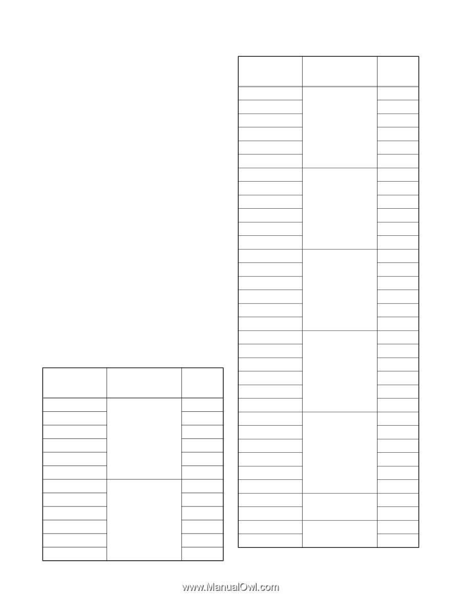
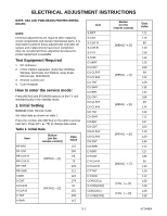
ELECTRICAL ADJUSTMENT INSTRUCTIONS NOTE: CBA AND PWB MEANS PRINTED WIRING BOARD. NOTE: Electrical adjustments are required after replacing circuit components and certain mechanical parts. It is important to perform these adjustments only after all repairs and replacements have been completed. Also, do not attempt these adjustments unless the proper equipment is available. Test Equipment Required 1. DC Voltmeter 2. NTSC Pattern Generator (Color Bar W/White Window, Red Color, Dot Pattern, Gray Scale, Monoscope, Multi-Burst) 3. Remote control unit 4. Color Analyzer How to enter the service mode: Press [MENU] and [POWER] buttons on the TV unit simultaneously in the standby mode. 1. Initial Setting General: Enter Service mode. Set initial data as shown on table 1. Press the number after [MENU] on the table to access next item. Press [CH. o / p] to change data value. Table 1: Initial Data Item RF-BRT RF-CNT RF-CLR-R RF-CLR-B RF-TNT RF-SHR V-BRT V-CNT V-CLR-R V-CLR-B V-TNT V-SHR Button (on the remote control) [MENU] → [1] [MENU] → [2] Data Value 122 200 65 75 129 112 122 174 81 101 135 112 Item S-BRT S-CNT S-CLR-R S-CLR-B S-TNT S-SHR D1-BRT D1-CNT D1-CLR-R D1-CLR-B D1-TNT D1-SHR D2-BRT D2-CNT D2-CLR-R D2-CLR-B D2-TNT D2-SHR D3-BRT D3-CNT D3-CLR-R D3-CLR-B D3-TNT D3-SHR DT-BRT DT-CNT DT-CLR-R DT-CLR-B DT-TNT DT-SHR COR(C/D1) C-COR(C/D2) COB(C/D1) C-COB(C/D2) Button (on the remote control) [MENU] → [3] [MENU] → [4] [MENU] → [5] [MENU] → [6] [MENU] → [7] [VOL -] → [1] [VOL -] → [3] Data Value 122 179 80 110 139 112 120 169 99 124 129 112 132 164 99 124 122 112 127 160 110 120 140 112 127 184 95 113 129 112 128 128 128 128 5-1 A7144EA
-
 1
1 -
2
-
3
-
4
-
5
-
6
-
7
-
8
-
 9
9 -
 10
10 -
 11
11 -
 12
12 -
 13
13 -
 14
14 -
 15
15 -
 16
16 -
 17
17 -
 18
18 -
 19
19 -
20
-
21
-
22
-
23
-
24
-
25
-
26
-
27
-
28
-
29
-
30
-
31
-
32
-
33
-
34
-
35
-
36
-
37
-
38
-
39
-
40
-
41
-
42
-
43
-
44
-
45
-
46
-
47
-
48
-
49
-
50
-
51
-
52
-
53
-
54
-
55
-
56
-
57
-
58
-
59
-
60
-
61
-
62
-
63
-
64
-
65
-
66
-
67
-
68
-
69
-
70
-
71
-
72
-
73
-
74
-
75
-
76
 |
 |