Sharp LC-20AV7U Service Manual - Page 36
List Of Caution, Notes, And Symbols Used In The Schematic Diagrams On, The Following S - repair
 |
View all Sharp LC-20AV7U manuals
Add to My Manuals
Save this manual to your list of manuals |
Page 36 highlights
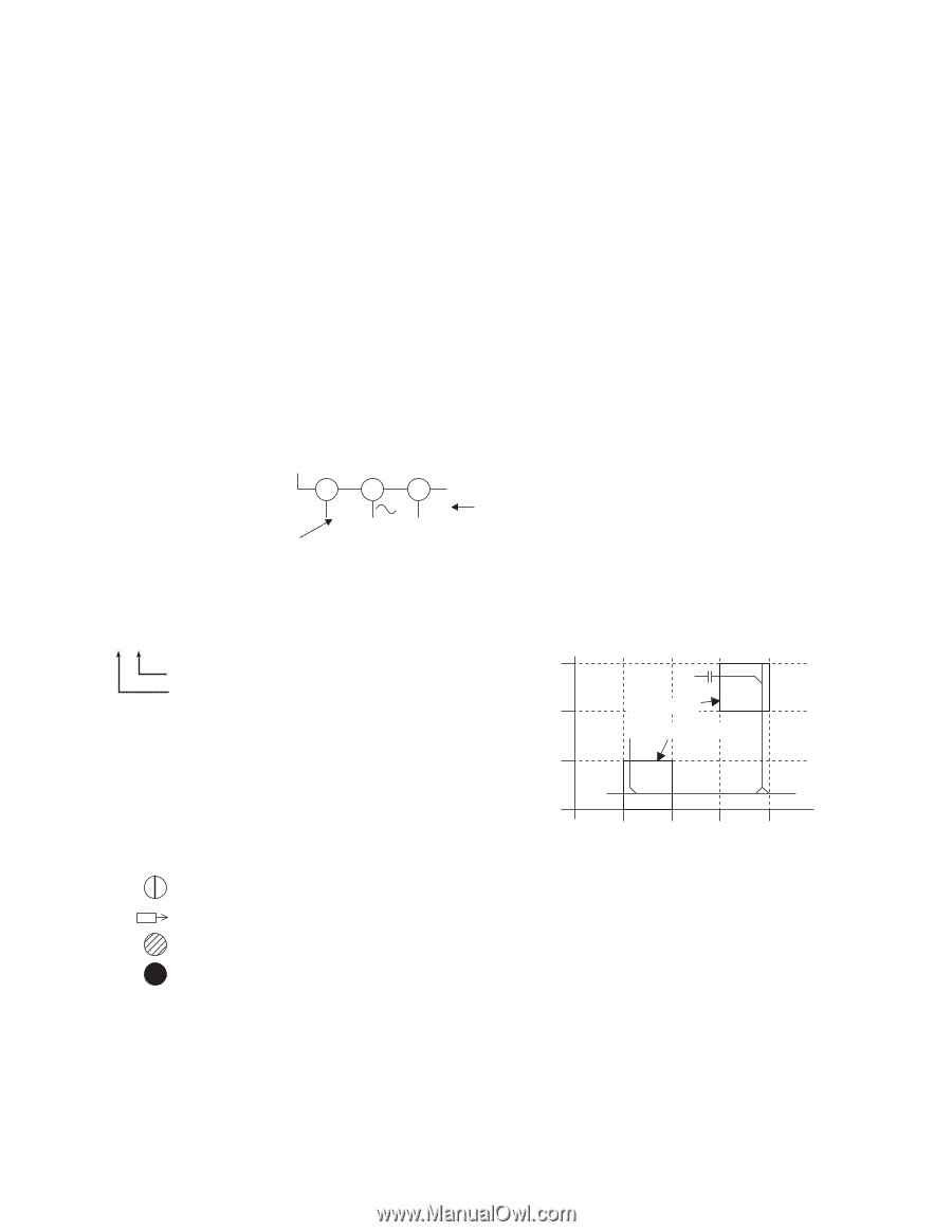
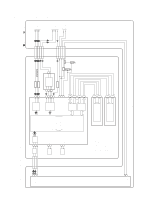
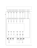
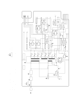
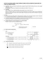
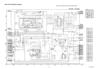
LIST OF CAUTION, NOTES, AND SYMBOLS USED IN THE SCHEMATIC DIAGRAMS ON THE FOLLOWING PAGES: 1. CAUTION: FOR CONTINUED PROTECTION AGAINST RISK OF FIRE, REPLACE ONLY WITH SAME TYPE_A,_V FUSE. ATTENTION: UTILISER UN FUSIBLE DE RECHANGE DE MEME TYPE DE_A,_V. 2. CAUTION: Fixed Voltage (or Auto voltage selectable) power supply circuit is used in this unit. If Main Fuse (F601) is blown, first check to see that all components in the power supply circuit are not defective before you connect the AC plug to the AC power supply. Otherwise it may cause some components in the power supply circuit to fail. 3. Note: (1) Do not use the part number shown on the drawings for ordering. The correct part number is shown in the parts list, and may be slightly different or amended since the drawings were prepared. (2) To maintain original function and reliability of repaired units, use only original replacement parts which are listed with their part numbers in the parts list section of the service manual. 4. Voltage indications on the schematics are as shown below: Plug the TV power cord into a standard AC outlet.: Voltage 1 2 5.0 3 5.0 Power on mode Indicates that the voltage is not consistent here. 5. How to read converged lines Unit: Volts 1-D3 Distinction Area Line Number (1 to 3 digits) 3 1-B1 AREA D3 Examples: 2 AREA B1 1. "1-D3" means that line number "1" goes to the line number "1" of the area "D3". 1 2. "1-B1" means that line number "1" goes to the line number 1-D3 "1" of the area "B1". ABCD 6. Test Point Information : Indicates a test point with a jumper wire across a hole in the PCB. : Used to indicate a test point with a component lead on foil side. : Used to indicate a test point with no test pin. : Used to indicate a test point with a test pin. 9-2 LCVSC
-
 1
1 -
2
-
3
-
4
-
5
-
6
-
7
-
8
-
9
-
10
-
11
-
12
-
13
-
14
-
15
-
16
-
17
-
18
-
19
-
20
-
21
-
22
-
23
-
24
-
25
-
26
-
27
-
28
-
29
-
30
-
 31
31 -
 32
32 -
 33
33 -
 34
34 -
 35
35 -
 36
36 -
 37
37 -
 38
38 -
 39
39 -
 40
40 -
 41
41 -
42
-
43
-
44
-
45
-
46
-
47
-
48
-
49
-
50
-
51
-
52
-
53
-
54
-
55
-
56
-
57
-
58
-
59
-
60
-
61
-
62
-
63
-
64
-
65
-
66
-
67
-
68
-
69
-
70
-
71
-
72
-
73
-
74
-
75
-
76
 |
 |