Sharp LC-20AV7U Service Manual - Page 15
White Balance Adjustment - remote
 |
View all Sharp LC-20AV7U manuals
Add to My Manuals
Save this manual to your list of manuals |
Page 15 highlights
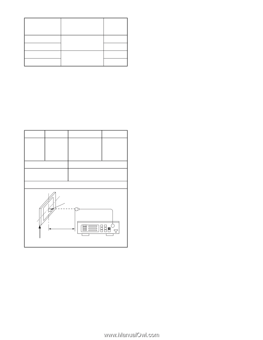
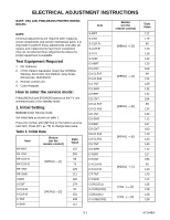
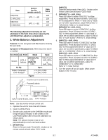
Item DR(C/D1) C-DR(C/D2) DB(C/D1) C-DB(C/D2) Button (on the remote control) [VOL -] → [4] [VOL -] → [6] Data Value 128 128 128 128 The following adjustment normally are not attempted in the field. Only when replacing the LCD Panel then adjust as a preparation. 2. White Balance Adjustment Purpose: To mix red, green and blue beams correctly for pure white. Symptom of Misadjustment: White becomes bluish or reddish. Test Point Adj. Point Mode Input Screen [VOL -] buttons [RF/INPUT1] C/D1 [INPUT2] C/D2 White Purity (APL 80%) or (APL 20%) M. EQ. Spec. Pattern Generator, Color analyzer x= 0.278 ± 0.005 y= 0.286 ± 0.005 Figure It carries out in a darkroom. Perpendicularity [INPUT2] Enter the Service mode. Press [VOL -] button on the remote control unit and select "C/D2" mode. 5. [RF/INPUT1]----(APL 80%) Press [6] button to select "DB(C/D1)" for Blue adjustment. Press [4] button to select "DR(C/D1)" for Red adjustment. When "x" value and "y" value are not within specification, adjust "DB (C/D1)" or "DR (C/D1)". Refer to "1. Initial Setting." [RF/INPUT1]----(APL 20%) Press [3] button to select "COB(C/D1)" for Blue adjustment. Press [1] button to select "COR(C/ D1)" for Red adjustment. When "x" value and "y" value are not within specification, adjust "COB (C/ D1)" or "COR (C/D1)". Refer to "1. Initial Setting." 6. [INPUT2]----(APL 80%) Press [6] button to select "C-DB(C/D2)" for Blue adjustment. Press [4] button to select "C-DR(C/ D2)" for Red adjustment.When "x" value and "y" value are not within specification, adjust "C-DB(C/ D2)" or "C-DR(C/D2)". Refer to "1. Initial Setting." [INPUT2]----(APL 20%) Press [3] button to select "C-COB(C/D2)" for Blue adjustment. Press [1] button to select "C-COR(C/ D2)" for Red adjustment.When "x" value and "y" value are not within specification, adjust "CCOB(C/D2)" or "C-COR(C/D2)". Refer to "1. Initial Setting." 7. Turn the power off and on again. (Main power button on the TV unit.) L = 3 cm INPUT: WHITE 80%, 20% Color Analyzer Note: Use the service remote control unit 1. Operate the unit for more than 20 minutes. 2. Input the White Purity. 3. Set the color analyzer to the CHROMA mode and bring the optical receptor to the center on the LCD-Panel surface after zero point calibration as shown above. Note: The optical receptor must be set perpendicularly to the LCD Panel surface. 4. [RF/INPUT1] Enter the Service mode. Press [VOL -] button on the remote control unit and select "C/D1" mode. 5-2 A7144EA
-
 1
1 -
2
-
3
-
4
-
5
-
6
-
7
-
8
-
9
-
 10
10 -
 11
11 -
 12
12 -
 13
13 -
 14
14 -
 15
15 -
 16
16 -
 17
17 -
 18
18 -
 19
19 -
 20
20 -
21
-
22
-
23
-
24
-
25
-
26
-
27
-
28
-
29
-
30
-
31
-
32
-
33
-
34
-
35
-
36
-
37
-
38
-
39
-
40
-
41
-
42
-
43
-
44
-
45
-
46
-
47
-
48
-
49
-
50
-
51
-
52
-
53
-
54
-
55
-
56
-
57
-
58
-
59
-
60
-
61
-
62
-
63
-
64
-
65
-
66
-
67
-
68
-
69
-
70
-
71
-
72
-
73
-
74
-
75
-
76
 |
 |