Sharp LC-20AV7U Service Manual - Page 41
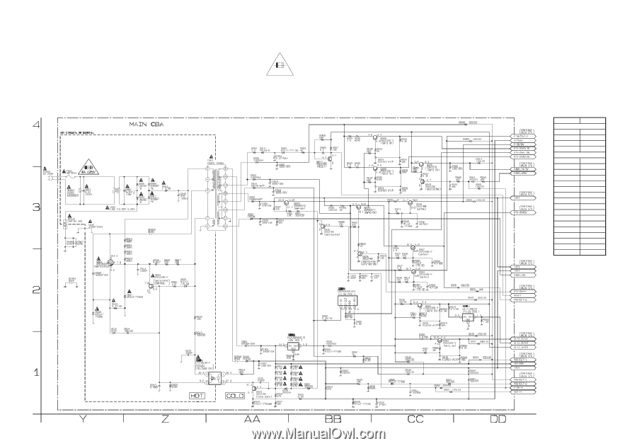
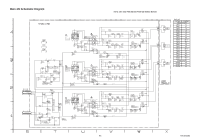
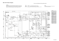
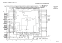
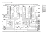
Main 5/5 Schematic Diagram
 |
View all Sharp LC-20AV7U manuals
Add to My Manuals
Save this manual to your list of manuals |
Page 41 highlights
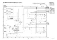
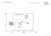
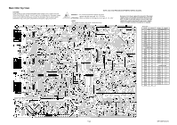
Main 5/5 Schematic Diagram CAUTION ! Fixed voltage (or Auto voltage selectable) power supply circuit is used in this unit. If Main Fuse (F601) is blown , check to see that all components in the power supply circuit are not defective before you connect the AC plug to the AC power supply. Otherwise it may cause some components in the power supply circuit to fail. NOTE: CBA AND PWB MEANS PRINTED WIRING BOARD. 4A/125V CAUTION ! : For continued protection against risk of fire, replace only with same type 4 A, 125V fuse. ATTENTION : Utiliser un fusible de rechange de même type de 4A, 125V. NOTE: The voltage for parts in hot circuit is measured using hot GND as a common terminal. MAIN 5/5 Ref No. Position ICS IC601 AA-1 IC901 DD-2 IC904 BB-2 IC905 BB-1 TRANSISTORS Q601 Y-2 Q603 Z-2 Q901 CC-1 Q902 CC-2 Q903 CC-2 Q905 BB-3 Q906 BB-2 Q907 CC-3 Q908 CC-4 Q909 CC-3 Q910 CC-4 Q913 AA-1 Q916 BB-3 Q917 BB-4 Q918 CC-3 Q919 CC-3 Q923 BB-3 9-7 A7144SCM5
-
 1
1 -
2
-
3
-
4
-
5
-
6
-
7
-
8
-
9
-
10
-
11
-
12
-
13
-
14
-
15
-
16
-
17
-
18
-
19
-
20
-
21
-
22
-
23
-
24
-
25
-
26
-
27
-
28
-
29
-
30
-
31
-
32
-
33
-
34
-
35
-
 36
36 -
 37
37 -
 38
38 -
 39
39 -
 40
40 -
 41
41 -
 42
42 -
 43
43 -
 44
44 -
 45
45 -
 46
46 -
47
-
48
-
49
-
50
-
51
-
52
-
53
-
54
-
55
-
56
-
57
-
58
-
59
-
60
-
61
-
62
-
63
-
64
-
65
-
66
-
67
-
68
-
69
-
70
-
71
-
72
-
73
-
74
-
75
-
76
 |
 |