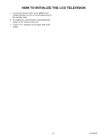
Sharp LC-20AV7U Service Manual - Page 18
Troubleshooting - digital
 |
View all Sharp LC-20AV7U manuals
Add to My Manuals
Save this manual to your list of manuals |
Page 18 highlights
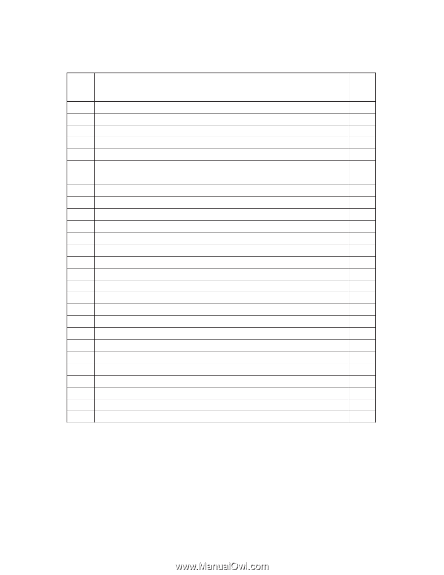
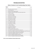
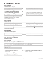
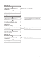
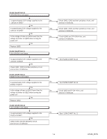
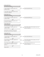
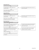
TROUBLESHOOTING Table of Contents for the Troubleshooting Flow Charts Flow Chart No. Description Page 1 The power cannot be turned on. 7-2 2 The fuse blows out. 7-2 3 When the output voltage fluctuates. 7-2 4 When buzz sound can be heard in the vicinity of power circuit. 7-2 5 +35V is not output. 7-2 6 VT+33V is not output. 7-3 7 INV+22V is not output. 7-3 8 DTV-ON+3.3V is not output. 7-3 9 DTV-ON+2.5V is not output. 7-3 10 DTV-ON+5V is not output. 7-3 11 AL+3.3V(D) is not output. 7-4 12 PANEL+3.3V is not output. 7-4 13 AL+1.2V(D) is not output. 7-4 14 AL+3.3V(A) is not output. 7-5 15 P-ON+5V(1) is not output. 7-5 16 +12V is not output. 7-5 17 P-ON+9V is not output. 7-5 18 DTV-ON+1.8V is not output. 7-6 19 PANEL-6V is not output. 7-6 20 The key operation is not functioning. 7-6 21 No operation is possible from the remote control unit. 7-7 22 Picture does not appear normally. (Tuner input (Analog) / Video input/S-Video input) 7-8 23 Picture does not appear normally. (Tuner input (Digital)) 7-8 24 Picture does not appear normally. (Y / Pb / Pr input) 7-8 25 Audio is not outputted normally. (Tuner input) 7-9 26 Audio is not outputted normally. (Tuner input (Digital)) 7-9 27 Audio is not outputted normally. (Audio input terminals) 7-10 NOTE: CBA AND PWB MEANS PRINTED WIRING BOARD. 7-1 A7144_45TS
-
 1
1 -
2
-
3
-
4
-
5
-
6
-
7
-
8
-
9
-
10
-
11
-
12
-
 13
13 -
 14
14 -
 15
15 -
 16
16 -
 17
17 -
 18
18 -
 19
19 -
 20
20 -
 21
21 -
 22
22 -
 23
23 -
24
-
25
-
26
-
27
-
28
-
29
-
30
-
31
-
32
-
33
-
34
-
35
-
36
-
37
-
38
-
39
-
40
-
41
-
42
-
43
-
44
-
45
-
46
-
47
-
48
-
49
-
50
-
51
-
52
-
53
-
54
-
55
-
56
-
57
-
58
-
59
-
60
-
61
-
62
-
63
-
64
-
65
-
66
-
67
-
68
-
69
-
70
-
71
-
72
-
73
-
74
-
75
-
76
 |
 |