Sharp LC-20AV7U Service Manual - Page 5
Standard Notes For Servicing - manual
 |
View all Sharp LC-20AV7U manuals
Add to My Manuals
Save this manual to your list of manuals |
Page 5 highlights
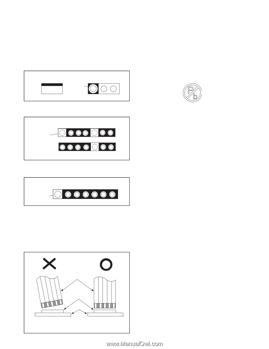
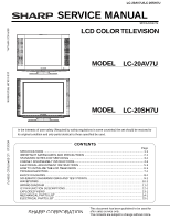
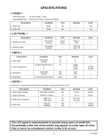
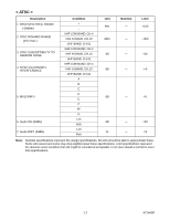
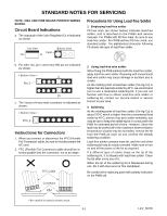
STANDARD NOTES FOR SERVICING NOTE: CBA AND PWB MEANS PRINTED WIRING BOARD. Circuit Board Indications a. The output pin of the 3 pin Regulator ICs is indicated as shown. Top View Input Out In Bottom View Precautions for Using Lead-free Solder 1 Employing lead-free solder Pb free mark (as shown below) indicates lead-free solder, and is attached on the PWBs and service manuals. For PWBs with Pb free mark, be sure to use lead-free solder. For PWB without Pb free mark, use standard solder. The alphabetical character following Pb shows the type of lead-free solder. b. For other ICs, pin 1 and every fifth pin are indicated as shown. < Bottom View > 5 Pin 1 10 c. The 1st pin of every male connector is indicated as shown. < Bottom View > Pin 1 Instructions for Connectors 1. When you connect or disconnect the FFC (Flexible Foil Connector) cable, be sure to first disconnect the AC cord. 2. FFC (Flexible Foil Connector) cable should be inserted parallel into the connector, not at an angle. FFC Cable Connector CBA 2 Using lead-free wire solder When fixing the PWB soldered with the lead-free solder, apply lead-free wire solder. Repairing with conventional lead wire solder may cause damage or accident due to cracks. As the melting point of lead-free solder (Sn-Ag-Cu) is higher than the lead wire solder by 40°C, we recommend you to use a dedicated soldering bit, if you are not familiar with how to obtain lead-free wire solder or soldering bit, contact our service station or service branch in your area. 3 Soldering As the melting point of lead-free solder (Sn-Ag-Cu) is about 220°C which is higher than the conventional lead solder by 40°C, and as it has poor solder wettability, you may be apt to keep the soldering bit in contact with the PWB for extended period of time. However, Since the land may be peeled off or the maximum heat-resistance temperature of parts may be exceeded, remove the bit from the PWB as soon as you confirm the steady soldering condition. Lead-free solder contains more tin, and the end of the soldering bit may be easily corroded. Make sure to turn on and off the power of the bit as required. If a different type of solder stays on the tip of the soldering bit, it is alloyed with lead-free solder. Clean the bit after every use of it. When the tip of the soldering bit is blackened during use, file it with steel wool or fine sandpaper. Be careful when replacing parts with polarity indication on the PWB silk. * Be careful to avoid a short circuit. 3-1 LCV_NOTE
-
 1
1 -
 2
2 -
 3
3 -
 4
4 -
 5
5 -
 6
6 -
 7
7 -
 8
8 -
 9
9 -
 10
10 -
 11
11 -
12
-
13
-
14
-
15
-
16
-
17
-
18
-
19
-
20
-
21
-
22
-
23
-
24
-
25
-
26
-
27
-
28
-
29
-
30
-
31
-
32
-
33
-
34
-
35
-
36
-
37
-
38
-
39
-
40
-
41
-
42
-
43
-
44
-
45
-
46
-
47
-
48
-
49
-
50
-
51
-
52
-
53
-
54
-
55
-
56
-
57
-
58
-
59
-
60
-
61
-
62
-
63
-
64
-
65
-
66
-
67
-
68
-
69
-
70
-
71
-
72
-
73
-
74
-
75
-
76
 |
 |