Sharp PG-M25X PGM25X Operation Manual - Page 33
Connecting to Video Equipment - model
 |
View all Sharp PG-M25X manuals
Add to My Manuals
Save this manual to your list of manuals |
Page 33 highlights
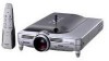
Setup and Connections Connecting to Video Equipment Connecting to Component Video Equipment Use a 3 RCA to 15-pin D-sub cable and DVI to 15-pin D-sub adaptor when connecting to the INPUT 1 terminal, component video equipment such as DVD players and DTV* decoders. *DTV is the umbrella term used to describe the new digital television system in the United States. 1 Connect the 3 RCA to 15-pin D- sub cable using the DVI to 15pin D-sub adaptor. 2 Use the above cables to con- nect the projector and the video equipment. 3 Connect the projector and the video equipment using a ø3.5 mm to RCA audio cable (commercially available). Note • When connecting the projector to the video equipment in this way, select "Component" for "Signal Type" in the "Picture" menu. See page 60. • A ø3.5 mm stereo minijack to RCA audio cable (commercially available) is required for audio input. Optional accessories 3RCA to 15-pin D-sub cable Type: AN-C3CP (9'10" (3.0 m)) DVI to 15-pin D-sub adaptor Model: AN-A1DV (7.9" (20 cm)) 3 ø3.5 mm to RCA audio cable (commercially available) To analog component output terminal To audio output terminal DVD player or DTV* decoder 2 3 RCA to 15-pin 1 DVI to 15-pin D-sub adaptor D-sub cable (sold separately) (sold separately) PG-M25X#E#p21_32.p65 29 02.4.29, 3:10 PM -29
-
 1
1 -
2
-
3
-
4
-
5
-
6
-
7
-
8
-
9
-
10
-
11
-
12
-
13
-
14
-
15
-
16
-
17
-
18
-
19
-
20
-
21
-
22
-
23
-
24
-
25
-
26
-
27
-
 28
28 -
 29
29 -
 30
30 -
 31
31 -
 32
32 -
 33
33 -
 34
34 -
 35
35 -
 36
36 -
 37
37 -
 38
38 -
39
-
40
-
41
-
42
-
43
-
44
-
45
-
46
-
47
-
48
-
49
-
50
-
51
-
52
-
53
-
54
-
55
-
56
-
57
-
58
-
59
-
60
-
61
-
62
-
63
-
64
-
65
-
66
-
67
-
68
-
69
-
70
-
71
-
72
-
73
-
74
-
75
-
76
-
77
-
78
-
79
-
80
-
81
-
82
-
83
-
84
-
85
-
86
-
87
-
88
-
89
-
90
-
91
-
92
-
93
-
94
-
95
-
96
-
97
-
98
-
99
-
100
-
101
-
102
-
103
-
104
-
105
-
106
-
107
-
108
-
109
-
110
-
111
-
112
-
113
-
114
-
115
-
116
-
117
-
118
-
119
-
120
-
121
-
122
-
123
-
124
-
125
-
126
-
127
-
128
-
129
-
130
 |
 |
