Sharp PN-G655U PNG655U Operation Manual - Page 31
RS-232C command table
 |
View all Sharp PN-G655U manuals
Add to My Manuals
Save this manual to your list of manuals |
Page 31 highlights
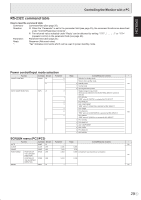
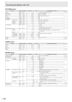
ENGLISH Controlling the Monitor with a PC RS-232C command table How to read the command table Command: Command field (See page 25.) Direction: W When the "Parameter" is set in the parameter field (see page 25), the command functions as described under "Control/Response Contents". R The returned value indicated under "Reply" can be obtained by setting "????", " ?" or "???+" (repeater control) in the parameter field (see page 25). Parameter: Parameter field (See page 25.) Reply: Response (Returned value) *: "Yes" indicates commands which can be used in power standby mode. Power control/Input mode selection Function POWER CONTROL INPUT MODE SELECTION Command Direction Parameter Reply Control/Response contents * POWR W 0 Switches to standby mode. 1 Returns from standby mode. R 0 Standby mode Yes 1 Normal mode 2 Input signal waiting mode INPS W 0 Toggle change for input mode Terminals not selected in DVI SELECT/BNC SELECT cannot be selected. 1 PC1 DIGITAL "ERR" when AV (DIGITAL) is selected for DVI SELECT. 2 PC2 ANALOG 3 AV2 COMPONENT "ERR" when PC (ANALOG) is selected for BNC SELECT. 4 AV3 VIDEO 6 PC3 ANALOG Yes "ERR" when AV (COMPONENT) is selected for BNC SELECT. 7 AV1 DIGITAL "ERR" when PC (DIGITAL) is selected for DVI SELECT. R 1 PC1 DIGITAL 2 PC2 ANALOG 3 AV2 COMPONENT 4 AV3 VIDEO 6 PC3 ANALOG 7 AV1 DIGITAL SCREEN menu (PC2/PC3) AUTO Function Command Direction ASNC W Parameter 1 Reply Control/Response contents * No CLOCK CLCK WR 0-255 0-255 PHASE PHSE WR 0-63 0-63 POSITIONING POSITION OF HPOS WR 0-500 0-500 A maximum value depends on a resolution. THE LONGEST No DIRECTION POSITION OF VPOS WR THE SHORTEST DIRECTION 0-100 0-100 RESET ARST W 1 No 29 E
-
 1
1 -
2
-
3
-
4
-
5
-
6
-
7
-
8
-
9
-
10
-
11
-
12
-
13
-
14
-
15
-
16
-
17
-
18
-
19
-
20
-
21
-
22
-
23
-
24
-
25
-
 26
26 -
 27
27 -
 28
28 -
 29
29 -
 30
30 -
 31
31 -
 32
32 -
 33
33 -
 34
34 -
 35
35 -
 36
36 -
37
-
38
-
39
-
40
-
41
-
42
-
43
-
44
-
45
-
46
-
47
-
48
-
49
-
50
-
51
-
52
-
53
-
54
-
55
-
56
-
57
-
58
-
59
-
60
-
61
-
62
-
63
-
64
-
65
-
66
-
67
-
68
-
69
-
70
-
71
-
72
-
73
-
74
-
75
-
76
 |
 |
