Sharp PN-K321 Operation Manual - Page 29
Initialization/Functional Restriction Setting FUNCTION menu, Others, Controlling the Monitor with
 |
View all Sharp PN-K321 manuals
Add to My Manuals
Save this manual to your list of manuals |
Page 29 highlights
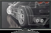
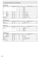
Controlling the Monitor with a PC (RS-232C) Initialization/Functional Restriction Setting (FUNCTION) menu Function Command Direction Parameter Reply Control/Response contents * ALL RESET RSET W 0 - ADJUSTMENT LOCK ALCK WR 0-2 0-2 0: OFF, 1:ON 1, 2:ON 2 ○ OSD DISPLAY LOSD WR 0-2 0-2 0: ON 1, 1: OFF, 2: ON 2 ○ LED OFLD WR 0-1 0-1 0: ON, 1: OFF ○ TEMPERATURE ALERT TALT WR 0-2 0-2 0: OFF, 1: OSD & LED, 2: LED ○ STATUS ALERT SALT WR 0-2 0-2 0: OFF, 1: OSD & LED, 2: LED ○ Others Function VOLUME BRIGHT TEMPERATURE SENSOR TEMPERATURE ACQUISITION CAUSE OF LAST STANDBY MODE Command VOLM VLMP DSTA Direction WR WR R Parameter 0-31 0-31 ERRT R STCA W 0 R Reply Control/Response contents * 0-31 ○ 0-31 ○ 0 Internal temperature normal 1 Internal temperature abnormal has occurred and the monitor is in standby mode 2 Internal temperature abnormal occurred (To delete the information of temperature abnormal, turn off the main power.) ● 3 Internal temperature abnormal has occurred and backlight brightness is dimmed 4 Temperature sensor abnormal Value Returns the temperature of the temperature sensor. Indicates a temperature sensor abnormality when "126" is returned. ○ Initialization 0 No detectable error has occurred 1 Standby mode by POWER button 2 Main power off by the main power switch 3 Standby mode by RS-232C ● 4 Input signal waiting mode by No Signal 6 Standby mode by abnormal temperature 20 Standby mode by OFF IF NO OPERATION setting 29 E
-
 1
1 -
2
-
3
-
4
-
5
-
6
-
7
-
8
-
9
-
10
-
11
-
12
-
13
-
14
-
15
-
16
-
17
-
18
-
19
-
20
-
21
-
22
-
23
-
 24
24 -
 25
25 -
 26
26 -
 27
27 -
 28
28 -
 29
29 -
 30
30 -
 31
31 -
 32
32 -
 33
33 -
 34
34 -
35
-
36
-
37
 |
 |