Sony EVI D100 Technical Manual - Page 5
Locations of Controls - evi
 |
UPC - 027242594364
View all Sony EVI D100 manuals
Add to My Manuals
Save this manual to your list of manuals |
Page 5 highlights
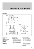
Locations of Controls Locations of Controls Main Unit Front 1 2 Rear 3 4 Bottom ON qs qd 12 5 6 7 1 POWER lamp 2 STANDBY lamp 3 Lens 4 Sensor for the remote commander 5 BACKUP switch 6 VIDEO jack 7 S VIDEO jack 8 IR SELECT switch 9 DC IN 12 V jack qf 8 9 q; qa 0 VISCA OUT jack qa VISCA IN jack qs IR SELECT switch Set this switch to ON to allow the camera output signals transmitted from the Remote Commander to the Color Video Camera via the VISCA OUT jack to be output. When you don't intend to do so, set it to OFF. qd D30/D31 mode switch Set this switch to ON to enable you to operate the Color Video Camera using the VISCA commands for the EVI-D30/D31. When you don't intend to do so, set it to OFF. Note You cannot use some of the commands of the EVI-D30/D31 even if you set this switch to ON. qf Tripod hole 5
-
 1
1 -
 2
2 -
 3
3 -
 4
4 -
 5
5 -
 6
6 -
 7
7 -
 8
8 -
 9
9 -
 10
10 -
 11
11 -
12
-
13
-
14
-
15
-
16
-
17
-
18
-
19
-
20
-
21
-
22
-
23
-
24
-
25
-
26
-
27
-
28
-
29
-
30
-
31
-
32
-
33
-
34
-
35
-
36
-
37
-
38
-
39
-
40
-
41
-
42
-
43
-
44
-
45
-
46
-
47
-
48
 |
 |
