Sony FW-75BZ30L Reference Guide - Page 5
FW-65BZ40L / 65BZ35L / 65BZ30L / 55BZ40L, 55BZ35L / 55BZ30L / 50BZ30L / 43BZ30L, EN
 |
View all Sony FW-75BZ30L manuals
Add to My Manuals
Save this manual to your list of manuals |
Page 5 highlights
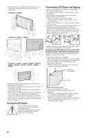
FW-65BZ40L / 65BZ35L / 65BZ30L / 55BZ40L / 55BZ35L / 55BZ30L / 50BZ30L / 43BZ30L 1 2 Screw hole on the rear cover VS (supplied) M6 machine screw (not supplied) Rope or chain (not supplied) Wall-anchor (not supplied) GENB 4 Screw (not supplied) 1.5 N·m {15 kgf·cm} The length of the M6 machine screw differs depending on the rope or chain diameter. Please refer to below illustration. 10 - 12 (mm) Screw (M6) Rope or chain VS 3 Anchor the LCD Display to the wall by using bolts, wall anchor and chain (or rope). FW-65BZ40L / 65BZ35L / 65BZ30L / 55BZ40L / 55BZ35L / 55BZ30L / 50BZ30L / 43BZ30L Wall-mount holes VS (supplied) Please refer to below illustration for M6 eye bolt length. 10 - 12 (mm) VS LCD Display's rear cover M6 eye bolt Note • Your LCD Display is shipped with screws attached to the rear of the LCD Display depending on the LCD Display model. (They are fastened in the screw holes for wall mounting.) Be sure to remove the upper two screws prior to anchoring the LCD Display to a wall. • Securing the LCD Display to the Stand without securing the LCD Display and the Stand to the wall provides minimum protection against the LCD Display toppling over. For further protection, be sure to follow the three measures recommended. Rope or chain (not supplied) M6 eye bolts (not supplied) 5EN
-
 1
1 -
 2
2 -
 3
3 -
 4
4 -
 5
5 -
 6
6 -
 7
7 -
 8
8 -
 9
9 -
 10
10 -
 11
11 -
12
-
13
-
14
-
15
-
16
-
17
-
18
-
19
-
20
-
21
-
22
-
23
-
24
-
25
-
26
-
27
-
28
-
29
-
30
-
31
-
32
-
33
-
34
-
35
-
36
-
37
-
38
-
39
-
40
-
41
-
42
-
43
-
44
-
45
-
46
-
47
-
48
-
49
-
50
-
51
-
52
-
53
-
54
-
55
-
56
-
57
-
58
-
59
-
60
-
61
-
62
-
63
-
64
-
65
-
66
-
67
-
68
 |
 |
