Sony HCD-GX8800 Operating Instructions - Page 8
System Control Jack
 |
View all Sony HCD-GX8800 manuals
Add to My Manuals
Save this manual to your list of manuals |
Page 8 highlights
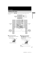
3 Connect the subwoofer (MHC-GN800 only). Connect the subwoofer cords to the SUBWOOFER terminals and the system cord to the SYSTEM CONTROL jack. Be sure to match the color of the cord and terminals/jacks. SUBWOOFER terminals Insert only the stripped portion. + Grey Grey/Solid (3) Black/Stripe (#) SYSTEM CONTROL jack To disconnect Notes • Be sure to make this connection before you connect the main unit's power cord to a wall outlet. • Place the subwoofer at least 0.3 meters (1 feet) away from the main unit. 4 Connect the FM and AM antennas. Set up the AM loop antenna, then connect it. 5 For models equipped with a voltage selector, set VOLTAGE SELECTOR to the position of your local power line voltage. VOLTAGE SELECTOR 230240V 220V 120V 6 Connect the power cord to a wall outlet. The demonstration appears in the display. When you press ?/1, the system turns on and the demonstration automatically ends. If the supplied adaptor on the plug does not fit your wall outlet, detach it from the plug (only for models equipped with an adaptor). To connect optional components See page 28. To attach the speaker pads Attach the supplied speaker pads to the bottom of the speakers to stabilize the speakers and to prevent them from slipping. FM75Ω COAXIAL -AM AM loop antenna Extend the FM lead antenna horizontally 8GB MHC-GN800 4-244-569-11 (1)
-
 1
1 -
2
-
 3
3 -
 4
4 -
 5
5 -
 6
6 -
 7
7 -
 8
8 -
 9
9 -
 10
10 -
 11
11 -
 12
12 -
 13
13 -
14
-
15
-
16
-
17
-
18
-
19
-
20
-
21
-
22
-
23
-
24
-
25
-
26
-
27
-
28
-
29
-
30
-
31
-
32
-
33
-
34
-
35
-
36
 |
 |
