TEAC DM-4800 DM-4800 Owner's Manual - Page 85
Digital trim, Delay, Stereo linking, DIGI. TRIM/DELAY, ENTER
 |
View all TEAC DM-4800 manuals
Add to My Manuals
Save this manual to your list of manuals |
Page 85 highlights
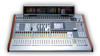
5 - Channel modules : Module setup Digital trim You can also set the digital trim value from a common screen. Press the DIGI. TRIM/DELAY key (ALT + key 0) to bring up the trim screen. in which delay is measured between samples and milliseconds. POD 3 and 4 and the ENTER key work in the same way as they do for the digital trim batch setup. Figure 5.16: Digital trim setting Use the cursor keys to select blocks of four channels and the PODs to set the values. You can also set all, odd-numbered, even-numbered or blocks of eight channels to the same value using the BATCH SETUP facility at the bottom of the screen. Use the ENTER key to SET the value set with the POD 3 encoder to the channels chosen with POD 4. Delay You can "slip" modules relative to each other in order to compensate for microphone placement, etc. This is the second tab of the DIGITAL TRIM/DELAY screen (it can also be set from the individual module screens). As with other screens, you can use the cursor to move around and highlight the settings for four modules, and the POD encoders to adjust these settings. The BATCH SETUP works in the same way as the digital trim described above, with a few additions. First, POD 1 can be used to change the position of the delay between pre-and post-fader for all channels. Additionally, POD 2's encoder changes the unit Stereo linking You can link two modules (channel modules, busses and aux sends) as stereo pairs when working with stereo input sources or stereo effect sends, etc. When modules are linked, setting the following parameters (where these are available) on one of the paired modules echoes the settings on the other module of the pair: • Digital trim • Gate settings Figure 5.17: Channel delay screen In addition to the channel delay, aux, buss and stereo modules can also have delay added. Figure 5.18: Master delay screen The operational difference between this and the channel delay screen is that the pre/post setting is not available on this screen. • Compressor settings and insertion point • EQ settings • Aux send levels/pan-balance setting/pickoff point • Mute • Fader level • Assignment • Delay time • Solo settings • Grouping TASCAM DM-4800 User's Manual 85
-
 1
1 -
2
-
3
-
4
-
5
-
6
-
7
-
8
-
9
-
10
-
11
-
12
-
13
-
14
-
15
-
16
-
17
-
18
-
19
-
20
-
21
-
22
-
23
-
24
-
25
-
26
-
27
-
28
-
29
-
30
-
31
-
32
-
33
-
34
-
35
-
36
-
37
-
38
-
39
-
40
-
41
-
42
-
43
-
44
-
45
-
46
-
47
-
48
-
49
-
50
-
51
-
52
-
53
-
54
-
55
-
56
-
57
-
58
-
59
-
60
-
61
-
62
-
63
-
64
-
65
-
66
-
67
-
68
-
69
-
70
-
71
-
72
-
73
-
74
-
75
-
76
-
77
-
78
-
79
-
 80
80 -
 81
81 -
 82
82 -
 83
83 -
 84
84 -
 85
85 -
 86
86 -
 87
87 -
 88
88 -
 89
89 -
 90
90 -
91
-
92
-
93
-
94
-
95
-
96
-
97
-
98
-
99
-
100
-
101
-
102
-
103
-
104
-
105
-
106
-
107
-
108
-
109
-
110
-
111
-
112
-
113
-
114
-
115
-
116
-
117
-
118
-
119
-
120
-
121
-
122
-
123
-
124
-
125
-
126
-
127
-
128
-
129
-
130
-
131
-
132
-
133
-
134
-
135
-
136
-
137
-
138
 |
 |
