TEAC NT-505 Owners Manual English Francais Espanol - Page 9
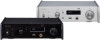
CLOCK SYNC input 10MHz IN connector, Power inlet ~IN
 |
View all TEAC NT-505 manuals
Add to My Manuals
Save this manual to your list of manuals |
Page 9 highlights
A ETHERNET port Connect a commercially-available LAN cable to this port when you want to connect this unit to a wired network or the Internet. oo When switching input sources, this port is labeled "NET". B OPTICAL digital audio input connector Use this to input digital audio. Connect the optical digital audio output connector of an audio device to it. Use a commercially-available optical digital cable with a square connector (TOSLINK) for connection. F USB port (rear) Use this to input digital audio from a computer. Connect it to a computer's USB port. Use a commercially-available USB2.0 cable (A-B type) for EN this connection. ATTENTION Before connecting a computer that is running a Windows OS, you must install the dedicated driver on the computer (page 25). Proper connection is not possible with a computer that does not have this driver installed. C RCA COAXIAL digital audio input connector Use this to input digital audio. Connect the coaxial digital audio output connector of an audio device to it. Use a commercially-available RCA coaxial digital cable for connection. D CLOCK SYNC input (10MHz IN) connector Use this to input a synchronization signal (clock sync). To input a 10MHz oscillator signal, connect the oscillator output here (page 29). Use a commercially available BNC coaxial cable for connection. oo Clock sync is only possible when the input source is USB or NET (including USB flash drives). E Analog audio output (LINE OUT) connectors These output 2 channels of analog audio. Connect these XLR or RCA connectors to a stereo amplifier or powered speakers. Use commercially available cables for connections. XLR: balanced XLR cables RCA: RCA audio cables Connect this unit's R connector to the R connector of the amplifier and its L connector to the L connector of the amplifier. oo See "Line output" on page 23 for analog output settings. G Maintenance port This is used for maintenance. Do not connect anything to this port unless instructed to do so by our service department. H Power inlet (~IN) Connect the supplied power cord here. After all other connections are complete, connect the power cord's plug to a wall outlet. VVDo not use any power cord other than the one included with this unit. Use of other power cords could result in fire or electric shock. VVUnplug the cord from the outlet when not using the unit for a long time. VVComplete all other connections before turn- ing the unit on. oo Carefully read the manuals of the devices that you are connecting and follow their instructions when making connections. oo Do not bundle connecting cables with power cords. Doing so could cause noise. oo Connect all plugs completely. 9
-
 1
1 -
2
-
3
-
 4
4 -
 5
5 -
 6
6 -
 7
7 -
 8
8 -
 9
9 -
 10
10 -
 11
11 -
 12
12 -
 13
13 -
 14
14 -
15
-
16
-
17
-
18
-
19
-
20
-
21
-
22
-
23
-
24
-
25
-
26
-
27
-
28
-
29
-
30
-
31
-
32
-
33
-
34
-
35
-
36
-
37
-
38
-
39
-
40
-
41
-
42
-
43
-
44
-
45
-
46
-
47
-
48
-
49
-
50
-
51
-
52
-
53
-
54
-
55
-
56
-
57
-
58
-
59
-
60
-
61
-
62
-
63
-
64
-
65
-
66
-
67
-
68
-
69
-
70
-
71
-
72
-
73
-
74
-
75
-
76
-
77
-
78
-
79
-
80
-
81
-
82
-
83
-
84
-
85
-
86
-
87
-
88
 |
 |
