Toshiba SD-V296 Owner's Manual - English - Page 10
Connections - instructions
 |
UPC - 022265001844
View all Toshiba SD-V296 manuals
Add to My Manuals
Save this manual to your list of manuals |
Page 10 highlights
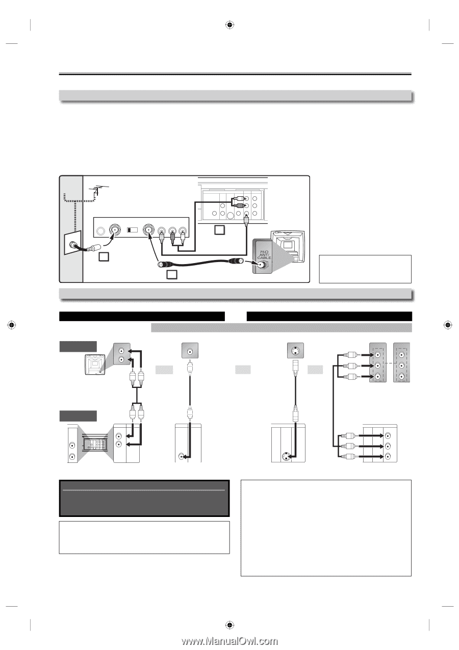
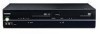
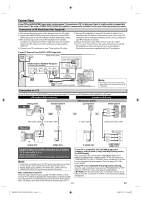
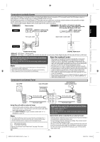
Connections If your TV has AUDIO/VIDEO input jacks, see the section "Connection to a TV" on this page. If not, it is still possible to connect this unit to your TV by using a STEREO AUDIO/VIDEO RF modulator (commercially available). In this case, follow the instructions below. Connection to RF Modulator (Not Supplied) 1) Disconnect the power cords of the devices from the AC outlet. 2) Connect the AUDIO/VIDEO output jacks of this unit to the AUDIO / VIDEO input jacks of your RF modulator by RCA Audio/Video cables. 3) The antenna input jack of your TV may have been already occupied. If so, disconnect the RF cable from your TV and then connect the RF cable to your RF modulator (usually marked "ANT IN"). 4) Connect your RF modulator to your TV by another RF cable. 5) Set your RF modulator's channel 3/4 switch to either 3 or 4, whichever the TV channel is least used in your area. If your RF modulator has a modulator/antenna switch, set it according to your RF modulator's manual. 6) Plug in the power cords of the devices to the AC outlet. 7) Turn on your TV and choose the same channel as you set the RF modulator's channel 3/4 switch to. For more details, follow the instructions supplied with the RF modulator. If your TV does not have AUDIO / VIDEO input jack. Cable Signal Antenna (Back of this unit) STEREO AUDIO / VIDEO RF Modulator (commercially available) AC 120V ANT IN CHANNEL TO TV VIDEO AUDIO 3 4 RL 2 DIGITAL AUDIO OUT DVD AUDIO OUT S-VIDEO OUT COMPONENT VIDEO OUT Y DVD/VCR VCR AUDIO OUT AUDIO IN L L L COAXIAL R CB/ PB R R VIDEO OUT VIDEO IN CR/ PR 1 RCA Audio/Video Cables (Supplied) (Back of TV) 3 RF Cable (commercially available) Antenna in jack Note: • The quality of picture may become poor if the unit is connected to an RF modulator. Connection to a TV If your TV does not have AUDIO/VIDEO input jack, see the section "Connecting to RF Modulator (Not Supplied)" on this page. VCR and Basic DVD Connection Available for DVD only analog audio TV AUDIO IN L standard picture VIDEO IN DVD's picture quality good picture S-VIDEO IN better picture COMPONENT VIDEO IN Y COMPONENT VIDEO IN Y AUDIO IN L R VIDEO IN R and CB PB or or or CR PR RCA audio cable RCA video cable S-video cable component video cable This unit DVD AUDIO OUT L R DIGITAL AUDIO OUT DVD AUDIO OUT S-VIDEO OUT COMPONENT VIDEO OUT Y DVD/VCR VCR AUDIO OUT AUDIO IN L L L COAXIAL R CB/ PB R R VIDEO OUT VIDEO IN CR/ PR DVD/VCR VCR AUDIO OUT L R or AUDIO OUT DVD/VCR VCR VIDEO OUT VIDEO OUT DIGITAL AUDIO OUT DVD AUDIO OUT S-VIDEO OUT COMPONENT VIDEO OUT COAXIAL S-VIDEO OUT DIGITAL AUDIO OUT DVD AUDIO OUT S-VIDEO OUT COMPONENT VIDEO OUT Y CB/ COAXIAL PB CR/ PR COMPONENT VIDEO OUT Supplied cables used in this connection are as follows: • RCA audio cable (L/R) x 1 • RCA video cable x 1 Please purchase the rest of the necessary cables at your local store. If your TV is compatible with 525 (480) progressive scanning, and you want to enjoy that high quality picture for DVD playing; You must select the connection COMPONENT VIDEO OUT above and progressive scanning mode. To set the mode, set "PROGRESSIVE" to "ON" in "DISPLAY" menu, so that the "P. SCAN" Note: • Connect this unit directly to your TV. If RCA audio/video cables are connected to a VCR, pictures may be distorted due to the copy protection system. on the front panel display appears. Refer to pages 23-24 for more details. If your TV is not compatible with progressive scanning; • DIGITAL AUDIO OUT (COAXIAL), DVD AUDIO OUT, S-VIDEO OUT and COMPONENT VIDEO OUT jacks are only useful in DVD mode. Use this unit in interlace mode and set "PROGRESSIVE" to "OFF" either in "DISPLAY" menu or by pressing and holding After connecting to your TV: Press the input selector button (usually TV/VIDEO, INPUT or AUX) on your TV to switch an appropriate external input channel (usually [ B (PLAY)] on the front of the unit on the DVD side for more than 5 seconds, so that the "P. SCAN" on the front panel display disappears. near channel 0) for viewing the picture from this unit. If the picture does not appear, also refer to the manual accompanying your TV. - 10 - EN E8EB5UD_SD-V296KU_EN_ES_v1.indd 10 2008/07/15 16:14:58
-
 1
1 -
2
-
3
-
4
-
 5
5 -
 6
6 -
 7
7 -
 8
8 -
 9
9 -
 10
10 -
 11
11 -
 12
12 -
 13
13 -
 14
14 -
 15
15 -
16
-
17
-
18
 |
 |