Toshiba Tecra 9000 Replacement Instructions
Toshiba Tecra 9000 Manual
 |
View all Toshiba Tecra 9000 manuals
Add to My Manuals
Save this manual to your list of manuals |
Toshiba Tecra 9000 manual content summary:
- Toshiba Tecra 9000 | Replacement Instructions - Page 1
FIELD REPLACEABLE UNIT DOCUMENTATION TM Tecra 9000 Series GENERAL INFORMATION Tools Required for Proper Disassembly and Reassembly: 1. Phillips battery and AC adaptor is not connected to the unit and the environment in which you are working on is protected from Electro-Static Discharge(ESD). TOSHIBA - Toshiba Tecra 9000 | Replacement Instructions - Page 2
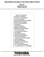
-R/W/DVD-ROM DRIVE DISASSEMBLY 5. MEMORY MODULE REMOVAL 6. BLUETOOTH CARD REMOVAL 7. HDD REMOVAL 8. KEYBOARD REMOVAL 9. MODEM BOARD REMOVAL 10 WIRELESS LAN CARD REMOVAL 11. TOP COVER REMOVAL 12. COOLING MODULE REMOVAL 13. CPU REMOVAL 14. MICROPHONE REMOVAL 15. SD/SOUND BOARD REMOVAL 16. RTC BATTERY - Toshiba Tecra 9000 | Replacement Instructions - Page 3
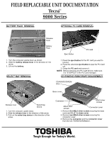
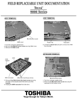
9000 Series BATTERY PACK REMOVAL OPTIONAL PC CARD REMOVAL Release lever Battery Pack Eject button PC card 1. Turn the computer upside down as shown. 2. Slide the battery release lever in the direction of the arrow. 3. Lift out the battery -R/W/DVD-ROM DRIVE DISASSEMBLY CD-R/W/DVD-ROM drive - Toshiba Tecra 9000 | Replacement Instructions - Page 4
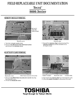
9000 Series MEMORY MODULE REMOVAL M2.5x2.8 silver flat head screws Memory cover 1. Turn the computer upside down. 2. Remove two M2.5x2.8 silver flat head screws and remove the memory cover. BLUETOOTH CARD REMOVAL Memory clips 3. Spread the memory the card. TOSHIBA Tough Enough for Today's World. - Toshiba Tecra 9000 | Replacement Instructions - Page 5
FIELD REPLACEABLE UNIT DOCUMENTATION TecraTM 9000 Series HDD REMOVAL HDD REMOVAL M2.5x8 silver screw HDD flat head screws securing the HDD to the bracket and lift the drive out of the bracket. 6. Unplug the HDD connector from the drive. M2.5x16 silver screw 1. Turn the computer upside down. 2. - Toshiba Tecra 9000 | Replacement Instructions - Page 6
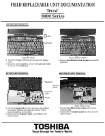
FIELD REPLACEABLE UNIT DOCUMENTATION TecraTM 9000 Series KEYBOARD REMOVAL Latch Keyboard Keyboard holder 2. Turn the computer right side up and open the brass screws securing the modem board. 2. Disconnect the modem board from PJ125 on the system board. TOSHIBA Tough Enough for Today's World. - Toshiba Tecra 9000 | Replacement Instructions - Page 7
9000 Series WIRELESS LAN CARD REMOVAL Mini-PCI connector clips Mini PCI cover M2.5x4 security torx screw 1. Remove one M2x4 security torx screw securing the mini PCIcover and lift out the cover. TOP COVER REMOVAL M2.5x8 silver screws Wireless slot. TOSHIBA Tough Enough for Today's World. - Toshiba Tecra 9000 | Replacement Instructions - Page 8
UNIT DOCUMENTATION TecraTM 9000 Series COOLING MODULE Sound board M2.5x4 brass screws 1. Disconnect the SD interface cable from PJ1001 and sound interface cable from PJ1000 on the SD/sound board. 2. Remove two M2.5x4 brass screws securing the SD/Sound board. 3. Lift out the SD/Sound board. TOSHIBA - Toshiba Tecra 9000 | Replacement Instructions - Page 9
FIELD REPLACEABLE UNIT DOCUMENTATION TecraTM 9000 Series RTC BATTERY REMOVAL LED/BLUETOOTH BOARD REMOVAL RTC battery M2.5x8 silver screw PJ5 from the top PCB: -Sound interface cable from PJ102 -SD interface cable from PJ103 -Modem cable from PJ126 TOSHIBA Tough Enough for Today's World. - Toshiba Tecra 9000 | Replacement Instructions - Page 10
UNIT DOCUMENTATION TecraTM 9000 Series BOTTOM PCB REMOVAL MEMBRANE SWITCH REMOVAL M2.5x4 brass screws Bottom board Membrane switch assy PJ18 Battery harness 1. Disconnect the battery harness from the left and right speakers. 2. Lift out the speakers. TOSHIBA Tough Enough for Today's World. - Toshiba Tecra 9000 | Replacement Instructions - Page 11
FIELD REPLACEABLE UNIT DOCUMENTATION TecraTM 9000 Series 14.1" DISPLAY MASK REMOVAL Latch FL INVERTER AND 14.1" LCD REMOVAL LCD module Display mask and disconnect the cable. 7. Remove four M2x2.8 silver screws securing the right and left LCD brackets. TOSHIBA Tough Enough for Today's World.
-
 1
1 -
 2
2 -
 3
3 -
 4
4 -
 5
5 -
 6
6 -
 7
7 -
8
-
9
-
10
-
11
 |
 |
FIELD REPLACEABLE UNIT DOCUMENTATION
9000 Series
Tecra
GENERAL INFORMATION
TM
Before attempting any of the following procedures,
make sure that the main battery and AC adaptor is
not connected to the unit and the environment in
which you are working on is protected from
Electro-Static Discharge(ESD).
TOSHIBA
Tough Enough for Today’s World.
Tools Required for Proper
Disassembly and Reassembly:
1. Phillips Screwdriver (Size 0&1)
2. Flat head Screwdriver
3. Security Torx (Size 7)
4. Case Separator
5. ESD Wrist Strap
6. ESD mats
7. Tweezers