Toshiba Tecra 9000 Replacement Instructions - Page 6
Keyboard Removal, Modem Board Removal
 |
View all Toshiba Tecra 9000 manuals
Add to My Manuals
Save this manual to your list of manuals |
Page 6 highlights
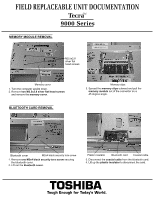
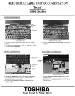
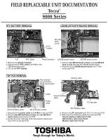
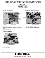
FIELD REPLACEABLE UNIT DOCUMENTATION TecraTM 9000 Series KEYBOARD REMOVAL Latch Keyboard Keyboard holder 2. Turn the computer right side up and open the display panel. 3. Using the case separator, unlatch the keyboard holder at the top of the keyboard. KEYBOARD REMOVAL M2.5x2.8 silver screws 4. Remove two M2.5x2.8 silver screws securing the keyboard. MODEM BOARD REMOVAL Keyboard Modem board Keyboard cable PJ123 5. Lift out the keyboard and set it as shown above(Place an insulator between the keyboard and the LCD to prevent scratches on the LCD). 6. Disconnect the keyboard cable from PJ123 on the system board. M2x4 brass screws 1. Remove two M2x4 brass screws securing the modem board. 2. Disconnect the modem board from PJ125 on the system board. TOSHIBA Tough Enough for Today's World.
-
 1
1 -
 2
2 -
 3
3 -
 4
4 -
 5
5 -
 6
6 -
 7
7 -
 8
8 -
 9
9 -
 10
10 -
 11
11
 |
 |
