Toshiba Tecra 9000 Replacement Instructions - Page 9
Rtc Battery Removal, Top Pcb Removal, Led/bluetooth Board Removal
 |
View all Toshiba Tecra 9000 manuals
Add to My Manuals
Save this manual to your list of manuals |
Page 9 highlights
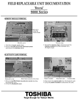
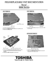
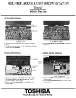
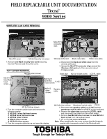
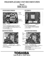
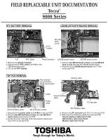
FIELD REPLACEABLE UNIT DOCUMENTATION TecraTM 9000 Series RTC BATTERY REMOVAL LED/BLUETOOTH BOARD REMOVAL RTC battery M2.5x8 silver screw PJ5 RTC cable Plastic insulator 1. Remove the plastic insulator. 2. Disconnect the RTC cable from PJ5 on the LED/Bluetooth board. 3. Lift out the RTC battery. LED/Bluetooth board M2.5x4 brass screws 1. Remove two M2.5x4 brass screws and one M2.5x8 silver screw securing the LED/Bluetooth board. 2. Disconnect the LED/Bluetooth board from PJ105 on the top PCB. TOP PCB REMOVAL This is where top and bottom board interconects Modem cable PJ801 Power cable Sound interface cable PC card slot M2.5x16 black screw M2.5x4 brass screws 1. Disconnect the power cable from PJ801 on the top PCB. 2. Remove two M2.5x4 brass screws and one M2.5x16 black screw securing the top PCB. 3. Gently lift up the right side of the top board to disconnect from PJ19 on the top PCB. SD interface cable 4. Remove the PC card slot from PJ117 on the top PCB. 5. Disconnect the following cables from the top PCB: -Sound interface cable from PJ102 -SD interface cable from PJ103 -Modem cable from PJ126 TOSHIBA Tough Enough for Today's World.
-
 1
1 -
2
-
3
-
 4
4 -
 5
5 -
 6
6 -
 7
7 -
 8
8 -
 9
9 -
 10
10 -
 11
11
 |
 |
