Toshiba Tecra 9000 Replacement Instructions - Page 7
Wireless Lan Card Removal, Top Cover Removal
 |
View all Toshiba Tecra 9000 manuals
Add to My Manuals
Save this manual to your list of manuals |
Page 7 highlights
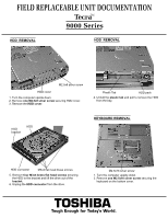
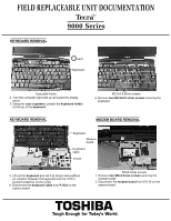
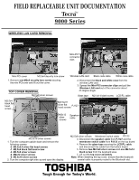
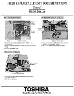
FIELD REPLACEABLE UNIT DOCUMENTATION TecraTM 9000 Series WIRELESS LAN CARD REMOVAL Mini-PCI connector clips Mini PCI cover M2.5x4 security torx screw 1. Remove one M2x4 security torx screw securing the mini PCIcover and lift out the cover. TOP COVER REMOVAL M2.5x8 silver screws Wireless LAN card Black coax cable White coax cable 2. Disconnect the black and white coax from the wireless LAN card. 3. Spread the Mini-PCI connector clips and pull the Wireless LAN card out of the connector about 45 degree angle. Glass tape M2.5x14 black screw LCD/FL cable M2.5x4 black flat head screw M2.5x2.8 silver flat PJ127 head screws M2x12 Speaker silver cable screws M2.5x16 silver screws 1. Turn the computer upside down and remove the following screws: -2 M2.5x2.8 silver flat head screws -1 M2.5x4 black flat head screw -4 M2.5x8 silver screws -4 M2x12 silver screws -6 M2.5x16 silver screws 2. Turn the computer right side up and open the display. M2.5x8 silver screws Membrane switch cable PJ122 3. Disconnect the speaker cable from PJ127 and the membrane switch cable from PJ122 on the top board 4. Remove the glass tape securing the LCD/FL cable and disconnect the cable from the bottom board. 5. Remove two M2.5x8 silver screws and one M2.5x14 black screw from the keyboard area. 5. Lift out the top cover assembly. Note: When installing the top cover, ensure that the bluetooth coaxial cable is properly routed to the Bluetooth slot. TOSHIBA Tough Enough for Today's World.
-
 1
1 -
 2
2 -
 3
3 -
 4
4 -
 5
5 -
 6
6 -
 7
7 -
 8
8 -
 9
9 -
 10
10 -
 11
11
 |
 |
