Toshiba Tecra 9000 Replacement Instructions - Page 11
Fl Inverter And 14.1 Lcd Removal, 1 Display Mask Removal
 |
View all Toshiba Tecra 9000 manuals
Add to My Manuals
Save this manual to your list of manuals |
Page 11 highlights
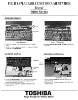
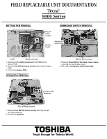
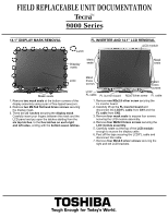
FIELD REPLACEABLE UNIT DOCUMENTATION TecraTM 9000 Series 14.1" DISPLAY MASK REMOVAL Latch FL INVERTER AND 14.1" LCD REMOVAL LCD module Display mask Mask seals Mask seals LCD Mask seals 1. Remove two mask seals at the bottom corners of the display assembly using a pair of fine-tipped tweezers. 2. Remove two M2.5x6 flat head brass screws securing the display mask. 3. There are 23 latches securing the display mask. Carefully insert your fingers between the mask and the LCD panel and pry open the latches starting from the six top latches, to the five latches on each right and left sides, ending with the bottom seven latches. M2x4 brass screws LCD/ FL cable FL inverter board M2x4 brass screws M2x3 silver screw FL cable 1. Remove one M2x2.8 silver screw securing the FL inverter board. 2. Carefully lift up the FL inverter board and disconnect the LCD/FL cable from CN1 and the FL cable from CN2. 3. Remove four mask seals to expose four screws securing the LCD module assembly. 4. Remove four M2X2.8 brass screws securing the LCD module assembly. 5. Carefully rotate out the top of the LCD module enough to access the display cable 6. Peel off the tape securing the LCD/FL cable and disconnect the cable. 7. Remove four M2x2.8 silver screws securing the right and left LCD brackets. TOSHIBA Tough Enough for Today's World.
-
 1
1 -
2
-
3
-
4
-
5
-
 6
6 -
 7
7 -
 8
8 -
 9
9 -
 10
10 -
 11
11
 |
 |
