Tripp Lite SU5000RT4UHV Owner's Manual for SmartOnline Single-Phase 5kVA-6kVA - Page 11
Connection, Hardwiring the Transformer Bundle Input/Output
 |
View all Tripp Lite SU5000RT4UHV manuals
Add to My Manuals
Save this manual to your list of manuals |
Page 11 highlights
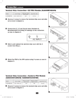
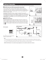
Connection (continued) 2 Connect the 2 sets of L1, L2 and Ground wires (1 Input, 1 Output) according to markings on the connectors as seen in diagram 2. Be sure to connect one set of wires to the input terminals and the other set to the output terminals. 2 3 Slide in and reattach the terminal strip cover with the 3 screws from Step 1. 3 4 Attach the PDU to the UPS system using 4 screws as seen in diagram 4. 4 Hardwiring the Transformer Bundle (Input/Output) SU6000RT4UTF 1. Plug the XFMR into the UPS. 2. Connect the transformer to the UPS. This can be a hardwire connection, outlet connection or both, provided the combined load does not exceed capacity. L1 G L2 208 / 240V Input L G N 120V Output Branch A N G L 120V Output Branch B SU12KRT4UHW See manual included with Parallel PDU for connection, setup and installation information. Set Front Panel Selector Switch to Proper Voltage Before Making Connections 11 201207113 933070.indb 11 9/17/2012 1:20:01 PM
-
 1
1 -
2
-
3
-
4
-
5
-
 6
6 -
 7
7 -
 8
8 -
 9
9 -
 10
10 -
 11
11 -
 12
12 -
 13
13 -
 14
14 -
 15
15 -
 16
16 -
17
-
18
-
19
-
20
-
21
-
22
-
23
-
24
-
25
-
26
-
27
-
28
-
29
-
30
-
31
-
32
-
33
-
34
-
35
-
36
-
37
-
38
-
39
-
40
-
41
-
42
-
43
-
44
-
45
-
46
-
47
-
48
-
49
-
50
-
51
-
52
-
53
-
54
-
55
-
56
-
57
-
58
-
59
-
60
-
61
-
62
-
63
-
64
-
65
-
66
-
67
-
68
-
69
-
70
-
71
-
72
-
73
-
74
-
75
-
76
-
77
-
78
-
79
-
80
-
81
-
82
-
83
-
84
-
85
-
86
-
87
-
88
-
89
-
90
-
91
-
92
-
93
-
94
-
95
-
96
-
97
-
98
-
99
-
100
-
101
-
102
-
103
-
104
-
105
-
106
-
107
-
108
-
109
-
110
-
111
-
112
-
113
-
114
-
115
-
116
 |
 |
