Troy-Bilt Storm 2620 Operation Manual - Page 9
Top View
 |
View all Troy-Bilt Storm 2620 manuals
Add to My Manuals
Save this manual to your list of manuals |
Page 9 highlights
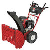
3. Place chute onto chute base and ensure chute control rod is positioned under the handle panel. Install hex bolt previously removed, but do not secure with wing nut at this time. See Fig. 3-8. 5. Rotate the joystick to the one o'clock position so that the silver indicator arrow on the pinion gear below the control panel faces upward. See Fig. 3-10. NOTE: The joystick will be angled slightly to the right at the one o'clock position. See "Top View" in Fig. 3-9. Figure 3-8 4. Squeeze the trigger on the joystick and rotate the chute by Figure 3-10 hand to face forward. The holes in the chute control input will be facing up. See Fig. 3-9. 6. Insert the chute control rod into the pinion gear below the joystick. Make sure to line up the hole in the rod with the NOTE: The chute will not rotate without squeezing the arrow on the pinion gear. See Fig. 3-11. trigger on the joystick. NOTE: The chute control rod will fit snuggly into the pinion gear. Support the rear of the dash panel with one hand Chute Control Input Top View while inserting the rod with your other hand to ensure the rod is inserted all the way into the pinion gear. NOTE: The hole is a reference for aligning the rod with the indicator arrow on the pinion gear, and will be visible after the rod has been inserted. Figure 3-9 Figure 3-11 Section 3 - Assembly & Set-Up 9
-
 1
1 -
2
-
3
-
 4
4 -
 5
5 -
 6
6 -
 7
7 -
 8
8 -
 9
9 -
 10
10 -
 11
11 -
 12
12 -
 13
13 -
 14
14 -
15
-
16
-
17
-
18
-
19
-
20
-
21
-
22
-
23
-
24
-
25
-
26
-
27
-
28
-
29
-
30
-
31
-
32
-
33
-
34
-
35
-
36
-
37
-
38
-
39
-
40
-
41
-
42
-
43
-
44
-
45
-
46
-
47
-
48
-
49
-
50
-
51
-
52
-
53
-
54
-
55
-
56
 |
 |
