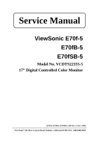
ViewSonic E70FSB-2 Service Manual - Page 5
ViewSonic Corporation, E70f-5_E70fB-5_E70fSB-5
 |
UPC - 766907870558
View all ViewSonic E70FSB-2 manuals
Add to My Manuals
Save this manual to your list of manuals |
Page 5 highlights
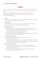
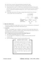
5-4 Move the resistor connection to each exposed metallic part and measure the voltage. 5-5 Reverse the polarity of the AC plug in the AC outlet and repeat the above measurement. 5-6 Voltage measured must not exceed 7.5 volt RMS, from any exposed metallic part to ground A leakage current tester may be used in the above hot check, in which case any current measured must not exceed 5.0 milliamp. In the case of a measurement exceeding the 5.0 milliamp value, a rework is required to eliminate the chance of shock hazard. Note: High voltage is present when this CRT display is operating. Always discharge the anode of the picture tube to the display chassis to prevent shock hazard. AC VOLTMETER TO INSTRUMENT'S EXPOSED METAL PARTS 0.15 F 1500 10W (EARTH GROUND) 6. IMPLOSION PROTECTION Fig. 1 Picture tubes are equipped with an integral implosion protection system, but care should be taken to avoid damage and scratching during installation. Use only Panasonic replacement picture tubes. 7. X-RADIATION WARNING:The only potential source of X-Radiation is the picture tube. However when the high voltage circuit is operating properly there is no possibility of X-Radiation problem. The basic precaution which must be exercised is to keep the high voltage at the following factory-recommended level. Note: It is important to use an accurate periodically calibrated high voltage meter. 7-1 The procedure for adjusting high voltage is shown on page 13. 7-2 If can not be adjust 25.0 KV at immediate service is required to prevent the possibility of premature component failure. 7-3 To prevent X-Radiation possibility it is essential to use the specified picture tube. IMPORTANT SAFETY NOTICE There are special components used in this CRT displays which are important for safety. These parts are identified ! by the international symbol on the schematic diagram and on the replacement parts list. It is essential that these critical parts should be replaced with manufacture's specified parts to prevent X-RADIATION, shock, fire, or other hazards. Do not modify the original design or this will void the original parts and labor guarantee. ViewSonic Corporation 2 Confidential - Do Not Copy E70f-5_E70fB-5_E70fSB-5
-
 1
1 -
 2
2 -
 3
3 -
 4
4 -
 5
5 -
 6
6 -
 7
7 -
 8
8 -
 9
9 -
 10
10 -
 11
11 -
12
-
13
-
14
-
15
-
16
-
17
-
18
-
19
-
20
-
21
-
22
-
23
-
24
-
25
-
26
-
27
-
28
-
29
-
30
-
31
-
32
-
33
-
34
-
35
-
36
-
37
-
38
-
39
-
40
-
41
-
42
-
43
-
44
-
45
-
46
-
47
-
48
-
49
-
50
-
51
-
52
-
53
-
54
-
55
-
56
-
57
-
58
-
59
-
60
-
61
-
62
-
63
-
64
-
65
-
66
-
67
-
68
-
69
-
70
-
71
-
72
-
73
-
74
-
75
-
76
-
77
-
78
-
79
-
80
-
81
-
82
-
83
-
84
-
85
-
86
-
87
-
88
-
89
-
90
-
91
-
92
-
93
-
94
-
95
-
96
-
97
-
98
-
99
-
100
-
101
-
102
-
103
 |
 |
