ViewSonic E70FSB-2 Service Manual - Page 8
Operating Instructions
 |
UPC - 766907870558
View all ViewSonic E70FSB-2 manuals
Add to My Manuals
Save this manual to your list of manuals |
Page 8 highlights
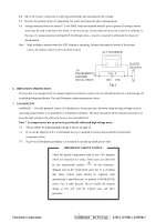
OPERATING INSTRUCTIONS This procedure gives you instructions for installing and using the Color display. 1. Position the display on the desired operation and plug the power cord into a convenient AC outlet. Three- wire power cord must be shielded and is provided as a safety precaution as it connects the chassis and cabinet to the electrical conduit ground. If the AC outlet in your location does not have provisions for the grounded type plug, the installer should attach the proper adapter to ensure a safe ground potential. 2. Connect the 15-pin color display shielded signal cable to your signal system device and lock both screws on the connector to ensure firm grounding. The connector information is as follow: 1 6 11 5 10 15 PIN NO. 1. 2. 3. 4. 5. 6. 7. 8. 15 - Pin Color Display Signal Cable DESCRIPTION PIN NO. DESCRIPTION RED GREEN BLUE GND GND GND-R GND-G GND-B 9. 5V From PC 10. Sync GND 11. NC 12. SDA 13. HORIZ. SYNC 14. VERT. SYNC ( VCLK) 15. SCL (DDC CLOCK) 3. Apply power to the display by turning the power switch to the "ON" position and allow about thirty seconds for display tube warm-up. The Power-On indicator lights when the display is on. 4. With proper signals feed to the display, a pattern or data should appear on the screen, adjust the brightness and contrast to the most pleasing display. 5. This monitor has power saving function following the VESA DPMS. Be sure to connect the signal cable to the PC. 6. If your color display requires service, it must be returned with the power cord. ViewSonic Corporation 5 Confidential - Do Not Copy E70f-5_E70fB-5_E70fSB-5
-
 1
1 -
2
-
 3
3 -
 4
4 -
 5
5 -
 6
6 -
 7
7 -
 8
8 -
 9
9 -
 10
10 -
 11
11 -
 12
12 -
 13
13 -
14
-
15
-
16
-
17
-
18
-
19
-
20
-
21
-
22
-
23
-
24
-
25
-
26
-
27
-
28
-
29
-
30
-
31
-
32
-
33
-
34
-
35
-
36
-
37
-
38
-
39
-
40
-
41
-
42
-
43
-
44
-
45
-
46
-
47
-
48
-
49
-
50
-
51
-
52
-
53
-
54
-
55
-
56
-
57
-
58
-
59
-
60
-
61
-
62
-
63
-
64
-
65
-
66
-
67
-
68
-
69
-
70
-
71
-
72
-
73
-
74
-
75
-
76
-
77
-
78
-
79
-
80
-
81
-
82
-
83
-
84
-
85
-
86
-
87
-
88
-
89
-
90
-
91
-
92
-
93
-
94
-
95
-
96
-
97
-
98
-
99
-
100
-
101
-
102
-
103
 |
 |
