Viking VBCV42381 Installation Instructions - Page 2
Warning, Caution - direct
 |
View all Viking VBCV42381 manuals
Add to My Manuals
Save this manual to your list of manuals |
Page 2 highlights
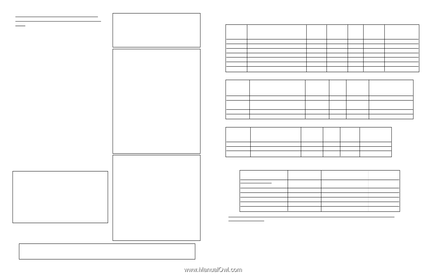
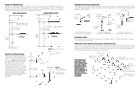
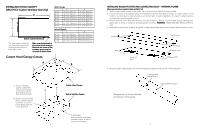
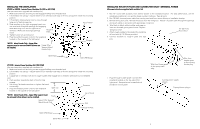
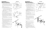
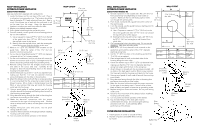
NOTE: IF INSTALLING HOOD WITH WARMING SHELF PANEL, INSTALL WARMING SHELF PANEL FIRST. IMPORTANT - PLEASE READ AND SAVE THESE INSTRUCTIONS •Before beginning, please read these instructions completely and carefully. •Do not remove permanently affixed labels, warnings, or plates from the product. This may void the warranty. •Please observe all local and national codes and ordinances. If no local codes are applicable, wire in accordance with the National Electrical Code, ANSI/NFPA 70-1990. •Outdoor approved models should be installed in a covered nonenclosed area and should be protected from the elements as much as possible. •The installer should leave these instructions with the consumer who should retain for local inspector's use and for future reference. •Check with a qualified and trained installer or local codes for makeup air requirement, if any. This hood is for residential installation only and is not designed for installation over a commercial product. Make sure power is off at the main circuit breaker or fuse box before making connections. To avoid risk of fire, electric shock, or injury to persons, turn off the electricity to the hood from the power supply before servicing or cleaning. Viking Range hoods are equipped with variable speed controls for blowers. These units will not function with a single speed ventilator. All Viking Range ventilator kits are designed specifically for use with Viking Range hoods. Use of any non-Viking Range ventilator kit will void the hood warranty. WARNING - TO REDUCE THE RISK OF FIRE, ELECTRIC SHOCK, OR INJURY TO PERSONS, OBSERVE THE FOLLOWING: 1. Use this unit only in the manner intended by the manufacturer. If you have any questions, contact the manufacturer. 2. Before servicing or cleaning unit, switch power off at service panel and lock service panel to prevent power from being switched on accidentally. When the service disconnecting means cannot be locked, securely fasten a prominent warning device, such as a tag, to the service panel. CAUTION TO REDUCE THE RISK OF FIRE, ELECTRICAL SHOCK, OR INJURY TO PERSONS, RANGEHOODS MUST BE INSTALLED WITH THE VENTILATORS THAT ARE SPECIFIED ON THEIR CARTON INDICATING SUITABILITY WITH THIS MODEL. OTHER VENTILATORS CANNOT BE SUBSTITUTED. WARNING TO REDUCE THE RISK OF FIRE, ELECTRICAL SHOCK, OR INJURY TO PERSONS, OBSERVE THE FOLLOWING: 1. Installation work and electrical wiring must be done by qualified person(s) in accordance with all applicable codes and standards, including fire-rated construction. 2. Sufficient air is needed for proper combustion and exhausting of gases through the flue (chimney) of fuel burning equipment to prevent back drafting. Follow the heating equipment manufacturer's guideline and safety standards such as those published by the National Fire Protection Association (NFPA), and the American Society for Heating, Refrigeration and Air Conditioning Engineers (ASHRAE), and the local code authorities. 3. When cutting or drilling into wall or ceiling, do not damage electrical wiring and other hidden utilities. 4. Ducted fans must always be vented to the outdoors. 5. WARNING!: To reduce the risk of fire, use only metal ductwork. 6. CAUTION!: To reduce risk of fire and to properly exhaust air, be sure to duct air outside. Do not vent exhaust air into spaces within walls or ceilings, or into attics, crawl spaces, or garages. WARNING - TO REDUCE THE RISK OF INJURY TO PERSONS IN THE EVENT OF A RANGETOP GREASE FIRE, OBSERVE THE FOLLOWING: (based on "Kitchen Firesafety Tips" published by NFPA) 1. SMOTHER FLAMES with a close-fitted lid, cookie sheet, or metal tray, then turn off the burner. BE CAREFUL TO PREVENT BURNS. If the flames do not go out immediately, EVACUATE AND CALL THE FIRE DEPARTMENT. 2. NEVER PICK UP A FLAMING PAN. You may be burned. 3. DO NOT USE WATER, including wet dishcloths or towels - a violent steam explosion will result. 4. Use an extinguisher ONLY if: •You know you have a Class ABC extinguisher, and you already know how to operate it. •The fire is small and contained in the area where it started. •The fire department is being called. •You can fight the fire with your back to an exit. IMPORTANT SERVICE INSTRUCTOINS -CAUTION- For general ventilating use only. Do not use to exhaust hazardous or explosive materials and vapors. 2 BASIC SPECIFICATIONS - INTERIOR AND EXTERIOR POWER HOODS 18" H. Indoor Wall Hoods DESCRIPTION RECOM. CFM1 (Int.-Interior; Ext.-Exterior) NUMBER OF 250 WATT HALOGEN HEAT LAMPS FILTERS LIGHTS (bulb sold separately) 24"W. 300 int./600 int./900 ext./1200 ext. 2 1 2 30" W. 300 int./600 int./1200 int./900 ext./1200 ext 2 1 2 36"W.* 300 int./600 int./1200 int./900 ext./1200 ext. 2 1 2 42"W.* 600 int./1200 int./900 ext./1200 ext. 2 1 2 48"W., 54"W.* 1200 int./1200 ext./1500 ext. 3 2 3 60"W.* 1200 int./1200 ext./1500 ext. 4 2 4 66"W.* 1200 int./1200 ext./1500 ext. 4 2 4 18" H. Indoor Island Hoods SPACERS 1 1 2 2 2 1 2 120VAC/60Hz MAX. AMPS3 (Interior/Exterior) 5.0/6.2/8.7/6.1 5.0/6.2/8.7/8.7/6.1 5.0/6.2/8.7/8.7/6.1 6.2/8.7/8.7/6.1 11.1/8.4/9.1 11.5/8.8/9.5 11.5/8.8/9.5 RECOM. DESCRIPTION CFM1 36"W.* 42"W.* 54"W.* 66"W.* (Int.-Interior; Ext.-Exterior) 600 int./1200 int./900 ext./1200 ext. 600 int./1200 int. 900 ext./1200 ext./1500 ext. 1200 int./1200 ext./1500 ext. 1200 int./1200 ext./1500 ext. NUMBER OF HALOGEN LIGHTS 4 4 6 8 FILTERS 4 4 6 8 SPACERS 2 4 4 4 120VAC/60Hz MAX. AMPS3 (Interior/Exterior) 4.9/7.4/7.4/4.7 4.9/7.4/4.8/5.4 8.2/5.6/6.2 9.0/6.3/7.1 18" H. Outdoor Wall Hoods* RECOM. DESCRIPTION CFM1 36"W. 48"W. 60"W. (Int.-Interior; Ext.-Exterior) 1200 int./1200 ext./1500 ext. 1200 int./1200 ext./1500 ext. 1200 int./1200 ext./1500 ext. NUMBER OF HALOGEN FILTERS LIGHTS 2 2 3 3 4 4 SPACERS 2 2 1 120VAC/60Hz MAX. AMPS3 (Interior/Exterior) 8.7/6.1/6.8 11.5/8.8/9.5 11.5/8.8/9.5 *1200 CFM interior or exterior or 1500 CFM exterior (if applicable) ventilator should be used with all outdoor approved models and when indoor models are installed over ranges/rangetops with gas grill. MODEL NUMBER For Use with hoods: VIV300 (interior) VIV600 (interior) VIV1200 (interior) VEV900 (exterior) VEV1200 (exterior) VEV1500 (exterior) CFM1 300 600 1200 900 1200 1500 RECOMMENDED DUCT SIZE 7" round 7" round 10" round 10" round 10" round 10" round MAX. DUCT RUN2 (ft.) 50 50 50 50 50 75 PROPER INSTALLATION/DUCTING IS EXTREMELY IMPORTANT TO ENSURE MAXIMUM PERFORMANCE FROM ANY VENTILATION PRODUCT 1. •All CFMs stated are based on tests at .1 static pressure: without applying static pressure, CFM would be greatly overstated. 2. •Duct run length is for general reference only; for longer duct runs, increase duct size and contact a qualified and trained installer. •Straight runs and gradual turns are best; for example, each 90o elbow is equivalent to 5-10 feet (1.52 - 3.05 m) of straight run. •Never use flexible duct; it creates back pressure/air turbulence and greatly reduces performance. •Proper performance is dependent upon proper ducting; make sure that a qualified and trained installer is used. •Check with a qualified and trained installer or local codes for makeup air requirement, if any. 3. •Max. amp rating for hoods includes recommended ventilator kit rating; all products must be hard wired direct with 2-wire with ground. 3
-
 1
1 -
 2
2 -
 3
3 -
 4
4 -
 5
5 -
 6
6 -
 7
7 -
 8
8 -
9
-
10
-
11
-
12
 |
 |