Viking VBCV42381 Installation Instructions - Page 6
Wall Installation, Exterior-power Ventilator, Roof Installation
 |
View all Viking VBCV42381 manuals
Add to My Manuals
Save this manual to your list of manuals |
Page 6 highlights
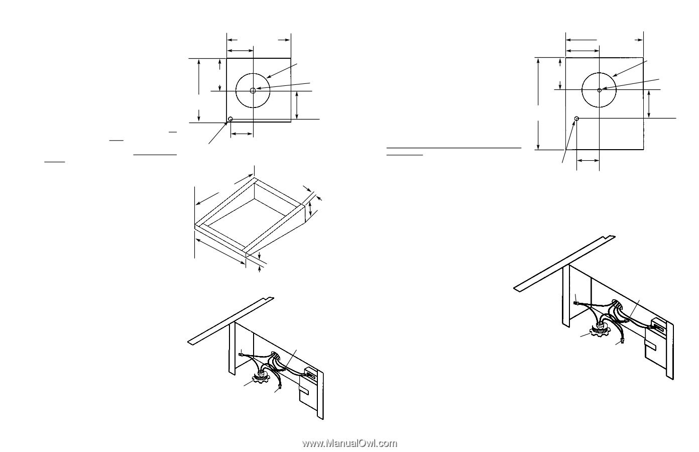
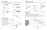
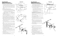
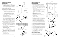
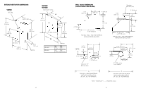
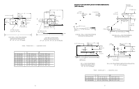
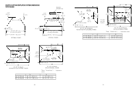
ROOF INSTALLATION EXTERIOR-POWER VENTILATOR VEV900-Exterior Power Ventilator Kit (900CFM) (also see instructions supplied with ventilator kit) 1. Locate the blower on the rear slope of the roof. Place it in a location to minimize duct run. The location should be free of obstacles (T.V. leads, electrical lines, etc.). Bear in mind, if the blower top is level with the roof peak, it will not be seen from the street. Keep this approximate location in mind as you work from within the attic. 2. Mark a point halfway between rafters. 3. Drill a guide hole through the roof at this point. 4. From the outside, use the guide hole as a starting point. A. Use a T-square to measure 81/2" (21.6 cm) to the left of the guide hole, then down 103/8" (26.4 cm) to locate the bottom left corner of the layout. B. Mark the rectangular cutout and remove only the shingles in this area. 5. Mark an 11" (27.9 cm) diameter circle centered on the guide hole and mark the center of the 11/4" (3.2 cm) diameter electrical wiring hole. 6. Cut out the roof board(s) along the 11" (27.9 cm) diameter circle and drill a 11/4" hole as marked. 7. For flat roof installations, build a curb that will mount the blower at a minimum pitch of 2/12. Discharge end of the blower should be pointed away from prevailing winds. 8. Remove roofing nails from the upper two-thirds of the shingles around the cutout area. Carefully lift the shingles to allow the back flashing sheet on the blower housing to fit under them. 9. Center the blower ring in the 11" (27.9 cm) diameter hole, making sure that the 11/4" (3.2 cm) diameter electrical wiring hold aligns with the hole in the wiring box. 10. Attach the blower to the roof with the six screws provided. It is recommende that the screws be located inside the blower housing. All six holes in the back panel must be filled, or any moisture that may get inside the housing could leak into the house. 11. Using a good grade of roofing cement, seal all of the shingles around the housing and flashing sheet as well as the mounting screw heads. 12. Bring electrical wiring through the hole in the wiring box and secure it according to local codes. 13. Make the electrical connections with the proper connector for the type of wiring being used. Connect white to white, black to black, and the green or bare wire to green. 14. Replace wiring box cover and screws. Do not pinch wiring under the cover. 15. Check for free movement of the damper before installing housing cover and screws. 16. Turn on power and check operation of the blower. 81/2" (21.6 cm) ROOF CUTOUT 203/4" (52.7 cm) 103/8" (26.4 cm) REMOVE SHINGLES 201/2" (52.1 cm) 11" (27.9 cm) dia. hole Guide Hole 91/8" (23.2 cm) 71/4" (18.4 cm) 11/4" (3.2 cm) dia. hole 281/4" (71.8 cm) 2"(5.1 cm) 25" (63.5 cm) 63/4" (17.1 cm) 2"(5.1 cm) Black to Black Green to Green 120 VAC Line In White to White 10 WALL INSTALLATION EXTERIOR-POWER VENTILATOR VEV900-Exterior-Power Ventilator Kit (900CFM) 1. Choose a position on the outside wall. Min. 24" (61.0 cm from ground may vary depending on local codes or location. Make sure that no wall studs, pipes or wires run through the opening area. 2. Drill a guide hole at the center of the opening area. 3. From the outside, use the guide hole as a starting point to lay out the installation. A. Use a T-square to measure 103/4" (27.3 cm) to the left of the guide hole, then 127/8" (32.7 cm) to locate the top-left corner of the layout. B. Starting from the top -left corner, mark a 25" (63.5 cm) by 281/2" (72.4 cm) rectangle on wall located from guide hole. 4. Cut a rectangular hole in the siding only. Do not cut the sheathing. Nail down all siding ends. 5. Mark an 11" (27.9 cm) diameter circle centered on the guide hole and mark the center of the 11/4" diameter electrical wiring hole. 6. Cut the 11" (27.9 cm) hole in the sheathing and drill the 11/4"(3.2 cm) as marked. 7. Place a large bead of caulk on the back side of the housing along the outer edge. 8. Center the blower ring in the 11" (27.9 cm) diameter hole, making sure that the 11/4" (3.2 cm) diameter electrical wiring hole aligns with the hole in the wiring box. 9. Attach blower to the wall with the six screws provided. It is recommended that the screws be located inside the blower housing. All six holes in the back panel must be filled, or any moisture that may get inside the housing could leak into the house. 10. Using a good grade of caulk, seal all around the mounting screw heads. WALL CUTOUT 103/4" (27.3 cm) 25" (63.5 cm) 12 7/8" (32.7 cm) 11" (27.9 cm) dia. hole Guide Hole 28 1/4" (71.8 cm) 91/8" (23.2 cm) 11/4" (3.2 cm) Dia. Hole 71/4" (18.4 cm) Black to Black Green to Green 11. Bring electrical wiring through the hole in the wiring box and secure it according to local codes. 12. Make the electrical connections with the proper connector for the type of wire being used. Connect white to white, black to black, and green or bare wire to green. 13. Replace wiring box cover and screws. Do not pinch wiring under cover. 14. Check for free movement of the damper before installing housing cover and screws. 15. Turn on power and check operation of the blower. 16. Top and side flanges of the back plate may be covered with trim strips. Do not block grill opening at bottom with trim. It will adversely affect performance of the blower. 11 120 VAC Line In White to White
-
 1
1 -
 2
2 -
 3
3 -
 4
4 -
 5
5 -
 6
6 -
 7
7 -
 8
8 -
 9
9 -
 10
10 -
 11
11 -
 12
12
 |
 |